Class Node
- All Implemented Interfaces:
Styleable,EventTarget
- Direct Known Subclasses:
com.sun.javafx.scene.AbstractNode,Camera,Canvas,ImageView,LightBase,Parent,Shape,Shape3D,SubScene
Each item in the scene graph is called a Node. Branch nodes are
of type Parent, whose concrete subclasses are Group,
Region, and Control,
or subclasses thereof.
Leaf nodes are classes such as
Rectangle, Text,
ImageView, MediaView,
or other such leaf classes which cannot have children. Only a single node within
each scene graph tree will have no parent, which is referred to as the "root" node.
There may be several trees in the scene graph. Some trees may be part of
a Scene, in which case they are eligible to be displayed.
Other trees might not be part of any Scene.
A node may occur at most once anywhere in the scene graph. Specifically,
a node must appear no more than once in all of the following:
as the root node of a Scene,
the children ObservableList of a Parent,
or as the clip of a Node.
The scene graph must not have cycles. A cycle would exist if a node is
an ancestor of itself in the tree, considering the Group content
ObservableList, Parent children ObservableList, and Node clip relationships
mentioned above.
If a program adds a child node to a Parent (including Group, Region, etc) and that node is already a child of a different Parent or the root of a Scene, the node is automatically (and silently) removed from its former parent. If a program attempts to modify the scene graph in any other way that violates the above rules, an exception is thrown, the modification attempt is ignored and the scene graph is restored to its previous state.
It is possible to rearrange the structure of the scene graph, for example, to move a subtree from one location in the scene graph to another. In order to do this, one would normally remove the subtree from its old location before inserting it at the new location. However, the subtree will be automatically removed as described above if the application doesn't explicitly remove it.
Node objects may be constructed and modified on any thread as long they are
not yet attached to a Scene in a Window that is
showing.
An application must attach nodes to such a Scene or modify them on the JavaFX
Application Thread.
The JavaFX Application Thread is created as part of the startup process for
the JavaFX runtime. See the Application class and
the Platform.startup(Runnable) method for more information.
String ID
Each node in the scene graph can be given a unique id. This id is
much like the "id" attribute of an HTML tag in that it is up to the designer
and developer to ensure that the id is unique within the scene graph.
A convenience function called lookup(String) can be used to find
a node with a unique id within the scene graph, or within a subtree of the
scene graph. The id can also be used identify nodes for applying styles; see
the CSS section below.
Coordinate System
The Node class defines a traditional computer graphics "local"
coordinate system in which the x axis increases to the right and the
y axis increases downwards. The concrete node classes for shapes
provide variables for defining the geometry and location of the shape
within this local coordinate space. For example,
Rectangle provides x, y,
width, height variables while
Circle provides centerX, centerY,
and radius.
At the device pixel level, integer coordinates map onto the corners and
cracks between the pixels and the centers of the pixels appear at the
midpoints between integer pixel locations. Because all coordinate values
are specified with floating point numbers, coordinates can precisely
point to these corners (when the floating point values have exact integer
values) or to any location on the pixel. For example, a coordinate of
(0.5, 0.5) would point to the center of the upper left pixel on the
Stage. Similarly, a rectangle at (0, 0) with dimensions
of 10 by 10 would span from the upper left corner of the
upper left pixel on the Stage to the lower right corner of the
10th pixel on the 10th scanline. The pixel center of the last pixel
inside that rectangle would be at the coordinates (9.5, 9.5).
In practice, most nodes have transformations applied to their coordinate
system as mentioned below. As a result, the information above describing
the alignment of device coordinates to the pixel grid is relative to
the transformed coordinates, not the local coordinates of the nodes.
The Shape class describes some additional
important context-specific information about coordinate mapping and how
it can affect rendering.
Transformations
Any Node can have transformations applied to it. These include
translation, rotation, scaling, or shearing.
A translation transformation is one which shifts the origin of the
node's coordinate space along either the x or y axis. For example, if you
create a Rectangle which is drawn at the origin
(x=0, y=0) and has a width of 100 and a height of 50, and then apply a
Translate with a shift of 10 along the x axis
(x=10), then the rectangle will appear drawn at (x=10, y=0) and remain
100 points wide and 50 tall. Note that the origin was shifted, not the
x variable of the rectangle.
A common node transform is a translation by an integer distance, most often used to lay out nodes on the stage. Such integer translations maintain the device pixel mapping so that local coordinates that are integers still map to the cracks between pixels.
A rotation transformation is one which rotates the coordinate space of
the node about a specified "pivot" point, causing the node to appear rotated.
For example, if you create a Rectangle which is
drawn at the origin (x=0, y=0) and has a width of 100 and height of 30 and
you apply a Rotate with a 90 degree rotation
(angle=90) and a pivot at the origin (pivotX=0, pivotY=0), then
the rectangle will be drawn as if its x and y were zero but its height was
100 and its width -30. That is, it is as if a pin is being stuck at the top
left corner and the rectangle is rotating 90 degrees clockwise around that
pin. If the pivot point is instead placed in the center of the rectangle
(at point x=50, y=15) then the rectangle will instead appear to rotate about
its center.
Note that as with all transformations, the x, y, width, and height variables of the rectangle (which remain relative to the local coordinate space) have not changed, but rather the transformation alters the entire coordinate space of the rectangle.
A scaling transformation causes a node to either appear larger or
smaller depending on the scaling factor. Scaling alters the coordinate space
of the node such that each unit of distance along the axis in local
coordinates is multiplied by the scale factor. As with rotation
transformations, scaling transformations are applied about a "pivot" point.
You can think of this as the point in the Node around which you "zoom". For
example, if you create a Rectangle with a
strokeWidth of 5, and a width and height of 50, and you apply a
Scale with scale factors (x=2.0, y=2.0) and
a pivot at the origin (pivotX=0, pivotY=0), the entire rectangle
(including the stroke) will double in size, growing to the right and
downwards from the origin.
A shearing transformation, sometimes called a skew, effectively rotates one axis so that the x and y axes are no longer perpendicular.
Multiple transformations may be applied to a node. Custom transforms are applied using the
transforms list. Predefined transforms are applied using the properties specified below.
The matrices that represent the transforms are multiplied in this order:
- Layout (
layoutX,layoutY) and translate (translateX,translateY,translateZ) - Rotate (
rotate) - Scale (
scaleX,scaleY,scaleZ) - Transforms list (
transforms) starting from element 0
Bounding Rectangles
Since every Node has transformations, every Node's geometric
bounding rectangle can be described differently depending on whether
transformations are accounted for or not.
Each Node has a read-only boundsInLocal
variable which specifies the bounding rectangle of the Node in
untransformed local coordinates. boundsInLocal includes the
Node's shape geometry, including any space required for a
non-zero stroke that may fall outside the local position/size variables,
and its clip and effect variables.
Each Node also has a read-only boundsInParent variable which
specifies the bounding rectangle of the Node after all transformations
have been applied as specified in the Transformations section.
It is called "boundsInParent" because the rectangle will be relative to the
parent's coordinate system. This is the 'visual' bounds of the node.
Finally, the layoutBounds variable defines the rectangular bounds of
the Node that should be used as the basis for layout calculations and
may differ from the visual bounds of the node. For shapes, Text, and ImageView,
layoutBounds by default includes only the shape geometry, including space required
for a non-zero strokeWidth, but does not include the effect,
clip, or any transforms. For resizable classes (Regions and Controls)
layoutBounds will always map to 0,0 width x height.
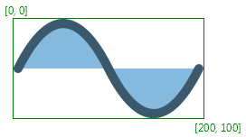
The image shows a node without any transformation and its boundsInLocal:
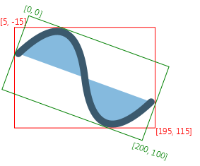
boundsInParent in the
coordinate space of the Node's parent. The boundsInLocal stays the same
as in the first image, the green rectangle in this image represents boundsInLocal
in the coordinate space of the Node.
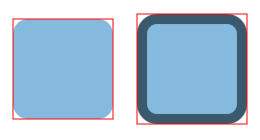
The images show a filled and stroked rectangle and their bounds. The
first rectangle [x:10.0 y:10.0 width:100.0 height:100.0 strokeWidth:0]
has the following bounds bounds: [x:10.0 y:10.0 width:100.0 height:100.0].
The second rectangle [x:10.0 y:10.0 width:100.0 height:100.0 strokeWidth:5]
has the following bounds: [x:7.5 y:7.5 width:105 height:105]
(the stroke is centered by default, so only half of it is outside
of the original bounds; it is also possible to create inside or outside
stroke).
Since neither of the rectangles has any transformation applied,
boundsInParent and boundsInLocal are the same.
CSS
The Node class contains id, styleClass, and
style variables that are used in styling this node from
CSS. The id and styleClass variables are used in
CSS style sheets to identify nodes to which styles should be
applied. The style variable contains style properties and
values that are applied directly to this node.
For further information about CSS and how to apply CSS styles to nodes, see the CSS Reference Guide.
- Since:
- JavaFX 2.0
-
Property Summary
PropertiesTypePropertyDescriptionfinal ObjectProperty<String> The accessible help text for thisNode.final ObjectProperty<String> The role description of thisNode.final ObjectProperty<AccessibleRole> The accessible role for thisNode.final ObjectProperty<String> The accessible text for thisNode.final ObjectProperty<BlendMode> TheBlendModeused to blend this individual node into the scene behind it.final ReadOnlyObjectProperty<Bounds> The rectangular bounds of thisNodein the node's untransformed local coordinate space.final ReadOnlyObjectProperty<Bounds> The rectangular bounds of thisNodein the parent coordinate system.final ObjectProperty<CacheHint> Additional hint for controlling bitmap caching.final BooleanPropertyA performance hint to the system to indicate that thisNodeshould be cached as a bitmap.final ObjectProperty<Node> Specifies aNodeto use to define the clipping shape for this Node.final ObjectProperty<Cursor> Defines the mouse cursor for thisNodeand subnodes.final ObjectProperty<DepthTest> Indicates whether depth testing is used when rendering this node.final ReadOnlyBooleanPropertyIndicates whether or not thisNodeis disabled.final BooleanPropertyDefines the individual disabled state of thisNode.The effective orientation of a node resolves the inheritance of node orientation, returning either left-to-right or right-to-left.final ObjectProperty<Effect> Specifies an effect to apply to thisNode.final ObjectProperty<EventDispatcher> Specifies the event dispatcher for this node.final ReadOnlyBooleanPropertyIndicates whether thisNodecurrently has the input focus.final BooleanPropertySpecifies whether thisNodeshould be a part of focus traversal cycle.final ReadOnlyBooleanPropertyIndicates whether thisNodeshould visibly indicate focus.final ReadOnlyBooleanPropertyIndicates whether thisNodeor any of its descendants currently has the input focus.final ReadOnlyBooleanPropertyWhether or not thisNodeis being hovered over.final StringPropertyThe id of thisNode.Property holding InputMethodRequests.final ReadOnlyObjectProperty<Bounds> The rectangular bounds that should be used for layout calculations for this node.final DoublePropertyDefines the x coordinate of the translation that is added to thisNode's transform for the purpose of layout.final DoublePropertyDefines the y coordinate of the translation that is added to thisNode's transform for the purpose of layout.final ReadOnlyObjectProperty<Transform> An affine transform that holds the computed local-to-parent transform.final ReadOnlyObjectProperty<Transform> An affine transform that holds the computed local-to-scene transform.final BooleanPropertyDefines whether or not this node's layout will be managed by it's parent.final BooleanPropertyIftrue, this node (together with all its children) is completely transparent to mouse events.final ObjectProperty<NodeOrientation> Node orientation describes the flow of visual data within a node.final ObjectProperty<EventHandler<? super ContextMenuEvent>> Defines a function to be called when a context menu has been requested on thisNode.final ObjectProperty<EventHandler<? super MouseEvent>> Defines a function to be called when drag gesture has been detected.final ObjectProperty<EventHandler<? super DragEvent>> Defines a function to be called when thisNodeis a drag and drop gesture source after its data has been dropped on a drop target.final ObjectProperty<EventHandler<? super DragEvent>> Defines a function to be called when the mouse button is released on thisNodeduring drag and drop gesture.final ObjectProperty<EventHandler<? super DragEvent>> Defines a function to be called when drag gesture enters thisNode.final ObjectProperty<EventHandler<? super DragEvent>> Defines a function to be called when drag gesture exits thisNode.final ObjectProperty<EventHandler<? super DragEvent>> Defines a function to be called when drag gesture progresses within thisNode.final ObjectProperty<EventHandler<? super InputMethodEvent>> Defines a function to be called when thisNodehas input focus and the input method text has changed.final ObjectProperty<EventHandler<? super KeyEvent>> Defines a function to be called when thisNodeor its childNodehas input focus and a key has been pressed.final ObjectProperty<EventHandler<? super KeyEvent>> Defines a function to be called when thisNodeor its childNodehas input focus and a key has been released.final ObjectProperty<EventHandler<? super KeyEvent>> Defines a function to be called when thisNodeor its childNodehas input focus and a key has been typed.final ObjectProperty<EventHandler<? super MouseEvent>> Defines a function to be called when a mouse button has been clicked (pressed and released) on thisNode.final ObjectProperty<EventHandler<? super MouseDragEvent>> Defines a function to be called when a full press-drag-release gesture enters thisNode.final ObjectProperty<EventHandler<? super MouseDragEvent>> Defines a function to be called when a full press-drag-release gesture leaves thisNode.final ObjectProperty<EventHandler<? super MouseEvent>> Defines a function to be called when a mouse button is pressed on thisNodeand then dragged.final ObjectProperty<EventHandler<? super MouseDragEvent>> Defines a function to be called when a full press-drag-release gesture progresses within thisNode.final ObjectProperty<EventHandler<? super MouseDragEvent>> Defines a function to be called when a full press-drag-release gesture ends (by releasing mouse button) within thisNode.final ObjectProperty<EventHandler<? super MouseEvent>> Defines a function to be called when the mouse enters thisNode.final ObjectProperty<EventHandler<? super MouseEvent>> Defines a function to be called when the mouse exits thisNode.final ObjectProperty<EventHandler<? super MouseEvent>> Defines a function to be called when mouse cursor moves within thisNodebut no buttons have been pushed.final ObjectProperty<EventHandler<? super MouseEvent>> Defines a function to be called when a mouse button has been pressed on thisNode.final ObjectProperty<EventHandler<? super MouseEvent>> Defines a function to be called when a mouse button has been released on thisNode.final ObjectProperty<EventHandler<? super RotateEvent>> Defines a function to be called when user performs a rotation action.final ObjectProperty<EventHandler<? super RotateEvent>> Defines a function to be called when a rotation gesture ends.final ObjectProperty<EventHandler<? super RotateEvent>> Defines a function to be called when a rotation gesture is detected.final ObjectProperty<EventHandler<? super ScrollEvent>> Defines a function to be called when a scrolling gesture ends.final ObjectProperty<EventHandler<? super ScrollEvent>> Defines a function to be called when user performs a scrolling action.final ObjectProperty<EventHandler<? super ScrollEvent>> Defines a function to be called when a scrolling gesture is detected.final ObjectProperty<EventHandler<? super SwipeEvent>> Defines a function to be called when a downward swipe gesture centered over this node happens.final ObjectProperty<EventHandler<? super SwipeEvent>> Defines a function to be called when a leftward swipe gesture centered over this node happens.final ObjectProperty<EventHandler<? super SwipeEvent>> Defines a function to be called when an rightward swipe gesture centered over this node happens.final ObjectProperty<EventHandler<? super SwipeEvent>> Defines a function to be called when an upward swipe gesture centered over this node happens.final ObjectProperty<EventHandler<? super TouchEvent>> Defines a function to be called when a touch point is moved.final ObjectProperty<EventHandler<? super TouchEvent>> Defines a function to be called when a new touch point is pressed.final ObjectProperty<EventHandler<? super TouchEvent>> Defines a function to be called when a touch point is released.final ObjectProperty<EventHandler<? super TouchEvent>> Defines a function to be called when a touch point stays pressed and still.final ObjectProperty<EventHandler<? super ZoomEvent>> Defines a function to be called when a zooming gesture ends.final ObjectProperty<EventHandler<? super ZoomEvent>> Defines a function to be called when user performs a zooming action.final ObjectProperty<EventHandler<? super ZoomEvent>> Defines a function to be called when a zooming gesture is detected.final DoublePropertySpecifies how opaque (that is, solid) theNodeappears.final ReadOnlyObjectProperty<Parent> The parent of thisNode.final BooleanPropertyDefines how the picking computation is done for this node when triggered by aMouseEventor acontainsfunction call.final ReadOnlyBooleanPropertyWhether or not theNodeis pressed.final DoublePropertyDefines the angle of rotation about theNode's center, measured in degrees.final ObjectProperty<Point3D> Defines the axis of rotation of thisNode.final DoublePropertyDefines the factor by which coordinates are scaled about the center of the object along the X axis of thisNode.final DoublePropertyDefines the factor by which coordinates are scaled about the center of the object along the Y axis of thisNode.final DoublePropertyDefines the factor by which coordinates are scaled about the center of the object along the Z axis of thisNode.final ReadOnlyObjectProperty<Scene> TheScenethat thisNodeis part of.final StringPropertyA string representation of the CSS style associated with this specificNode.final DoublePropertyDefines the x coordinate of the translation that is added to thisNode's transform.final DoublePropertyDefines the y coordinate of the translation that is added to thisNode's transform.final DoublePropertyDefines the Z coordinate of the translation that is added to the transformed coordinates of thisNode.final DoublePropertyDefines the rendering and picking order of thisNodewithin its parent.final BooleanPropertySpecifies whether thisNodeand any subnodes should be rendered as part of the scene graph. -
Field Summary
FieldsModifier and TypeFieldDescriptionstatic final doubleThis is a special value that might be returned bygetBaselineOffset(). -
Constructor Summary
Constructors -
Method Summary
Modifier and TypeMethodDescriptionfinal ObjectProperty<String> The accessible help text for thisNode.final ObjectProperty<String> The role description of thisNode.final ObjectProperty<AccessibleRole> The accessible role for thisNode.final ObjectProperty<String> The accessible text for thisNode.final <T extends Event>
voidaddEventFilter(EventType<T> eventType, EventHandler<? super T> eventFilter) Registers an event filter for this target.final <T extends Event>
voidaddEventHandler(EventType<T> eventType, EventHandler<? super T> eventHandler) Registers an event handler for this target.final voidapplyCss()If required, apply styles to this Node and its children, if any.final voidautosize()If the node is resizable, will set its layout bounds to its current preferred width and height.final ObjectProperty<BlendMode> TheBlendModeused to blend this individual node into the scene behind it.final ReadOnlyObjectProperty<Bounds> The rectangular bounds of thisNodein the node's untransformed local coordinate space.final ReadOnlyObjectProperty<Bounds> The rectangular bounds of thisNodein the parent coordinate system.Construct an event dispatch chain for this target.final ObjectProperty<CacheHint> Additional hint for controlling bitmap caching.final BooleanPropertyA performance hint to the system to indicate that thisNodeshould be cached as a bitmap.final ObjectProperty<Node> Specifies aNodeto use to define the clipping shape for this Node.doubleReturns the area of thisNodeprojected onto the physical screen in pixel units.booleancontains(double localX, double localY) Returnstrueif the given point (specified in the local coordinate space of thisNode) is contained within the shape of thisNode.booleanReturnstrueif the given point (specified in the local coordinate space of thisNode) is contained within the shape of thisNode.final ObjectProperty<Cursor> Defines the mouse cursor for thisNodeand subnodes.final ObjectProperty<DepthTest> Indicates whether depth testing is used when rendering this node.final ReadOnlyBooleanPropertyIndicates whether or not thisNodeis disabled.final BooleanPropertyDefines the individual disabled state of thisNode.The effective orientation of a node resolves the inheritance of node orientation, returning either left-to-right or right-to-left.final ObjectProperty<Effect> Specifies an effect to apply to thisNode.final ObjectProperty<EventDispatcher> Specifies the event dispatcher for this node.voidexecuteAccessibleAction(AccessibleAction action, Object... parameters) This method is called by the assistive technology to request the action indicated by the argument should be executed.final voidFires the specified event.final ReadOnlyBooleanPropertyIndicates whether thisNodecurrently has the input focus.final BooleanPropertySpecifies whether thisNodeshould be a part of focus traversal cycle.final ReadOnlyBooleanPropertyIndicates whether thisNodeshould visibly indicate focus.final ReadOnlyBooleanPropertyIndicates whether thisNodeor any of its descendants currently has the input focus.final StringGets the value of theaccessibleHelpproperty.final AccessibleRoleGets the value of theaccessibleRoleproperty.final StringGets the value of theaccessibleRoleDescriptionproperty.final StringGets the value of theaccessibleTextproperty.doubleThe 'alphabetic' (or 'roman') baseline offset from the node's layoutBounds.minY location that should be used when this node is being vertically aligned by baseline with other nodes.final BlendModeGets the value of theblendModeproperty.final BoundsGets the value of theboundsInLocalproperty.final BoundsGets the value of theboundsInParentproperty.final CacheHintGets the value of thecacheHintproperty.static List<CssMetaData<? extends Styleable, ?>> Gets theCssMetaDataassociated with this class, which may include theCssMetaDataof its superclasses.final NodegetClip()Gets the value of theclipproperty.Returns the orientation of a node's resizing bias for layout purposes.List<CssMetaData<? extends Styleable, ?>> This method should delegate togetClassCssMetaData()so that a Node's CssMetaData can be accessed without the need for reflection.final CursorGets the value of thecursorproperty.final DepthTestGets the value of thedepthTestproperty.final EffectGets the value of theeffectproperty.final NodeOrientationGets the value of theeffectiveNodeOrientationproperty.final EventDispatcherGets the value of theeventDispatcherproperty.final StringgetId()The id of thisNode.protected CursorReturns the initial cursor state of this node, for use by the JavaFX CSS engine to correctly set its initial value.protected BooleanReturns the initial focus traversable state of this node, for use by the JavaFX CSS engine to correctly set its initial value.final InputMethodRequestsGets the value of theinputMethodRequestsproperty.final BoundsGets the value of thelayoutBoundsproperty.final doubleGets the value of thelayoutXproperty.final doubleGets the value of thelayoutYproperty.final TransformGets the value of thelocalToParentTransformproperty.final TransformGets the value of thelocalToSceneTransformproperty.final NodeOrientationGets the value of thenodeOrientationproperty.final EventHandler<? super ContextMenuEvent> Gets the value of theonContextMenuRequestedproperty.final EventHandler<? super MouseEvent> Gets the value of theonDragDetectedproperty.final EventHandler<? super DragEvent> Gets the value of theonDragDoneproperty.final EventHandler<? super DragEvent> Gets the value of theonDragDroppedproperty.final EventHandler<? super DragEvent> Gets the value of theonDragEnteredproperty.final EventHandler<? super DragEvent> Gets the value of theonDragExitedproperty.final EventHandler<? super DragEvent> Gets the value of theonDragOverproperty.final EventHandler<? super InputMethodEvent> Gets the value of theonInputMethodTextChangedproperty.final EventHandler<? super KeyEvent> Gets the value of theonKeyPressedproperty.final EventHandler<? super KeyEvent> Gets the value of theonKeyReleasedproperty.final EventHandler<? super KeyEvent> Gets the value of theonKeyTypedproperty.final EventHandler<? super MouseEvent> Gets the value of theonMouseClickedproperty.final EventHandler<? super MouseDragEvent> Gets the value of theonMouseDragEnteredproperty.final EventHandler<? super MouseDragEvent> Gets the value of theonMouseDragExitedproperty.final EventHandler<? super MouseEvent> Gets the value of theonMouseDraggedproperty.final EventHandler<? super MouseDragEvent> Gets the value of theonMouseDragOverproperty.final EventHandler<? super MouseDragEvent> Gets the value of theonMouseDragReleasedproperty.final EventHandler<? super MouseEvent> Gets the value of theonMouseEnteredproperty.final EventHandler<? super MouseEvent> Gets the value of theonMouseExitedproperty.final EventHandler<? super MouseEvent> Gets the value of theonMouseMovedproperty.final EventHandler<? super MouseEvent> Gets the value of theonMousePressedproperty.final EventHandler<? super MouseEvent> Gets the value of theonMouseReleasedproperty.final EventHandler<? super RotateEvent> Gets the value of theonRotateproperty.final EventHandler<? super RotateEvent> Gets the value of theonRotationFinishedproperty.final EventHandler<? super RotateEvent> Gets the value of theonRotationStartedproperty.final EventHandler<? super ScrollEvent> Gets the value of theonScrollproperty.final EventHandler<? super ScrollEvent> Gets the value of theonScrollFinishedproperty.final EventHandler<? super ScrollEvent> Gets the value of theonScrollStartedproperty.final EventHandler<? super SwipeEvent> Gets the value of theonSwipeDownproperty.final EventHandler<? super SwipeEvent> Gets the value of theonSwipeLeftproperty.final EventHandler<? super SwipeEvent> Gets the value of theonSwipeRightproperty.final EventHandler<? super SwipeEvent> Gets the value of theonSwipeUpproperty.final EventHandler<? super TouchEvent> Gets the value of theonTouchMovedproperty.final EventHandler<? super TouchEvent> Gets the value of theonTouchPressedproperty.final EventHandler<? super TouchEvent> Gets the value of theonTouchReleasedproperty.final EventHandler<? super TouchEvent> Gets the value of theonTouchStationaryproperty.final EventHandler<? super ZoomEvent> Gets the value of theonZoomproperty.final EventHandler<? super ZoomEvent> Gets the value of theonZoomFinishedproperty.final EventHandler<? super ZoomEvent> Gets the value of theonZoomStartedproperty.final doubleGets the value of theopacityproperty.final ParentGets the value of theparentproperty.final ObservableMap<Object, Object> Returns an observable map of properties on this node for use primarily by application developers.final ObservableSet<PseudoClass> Return the pseudo-class state of this Styleable.final doubleGets the value of therotateproperty.final Point3DGets the value of therotationAxisproperty.final doubleGets the value of thescaleXproperty.final doubleGets the value of thescaleYproperty.final doubleGets the value of thescaleZproperty.final ScenegetScene()Gets the value of thesceneproperty.final StringgetStyle()A string representation of the CSS style associated with this specificNode.Return the parent of this Styleable, or null if there is no parent.final ObservableList<String> A list of String identifiers which can be used to logically group Nodes, specifically for an external style engine.final ObservableList<Transform> final doubleGets the value of thetranslateXproperty.final doubleGets the value of thetranslateYproperty.final doubleGets the value of thetranslateZproperty.The type of thisStyleablethat is to be used in selector matching.Returns a previously set Object property, or null if no such property has been set using thesetUserData(java.lang.Object)method.final doubleGets the value of theviewOrderproperty.booleanTests if Node has properties.final ReadOnlyBooleanPropertyWhether or not thisNodeis being hovered over.final StringPropertyThe id of thisNode.Property holding InputMethodRequests.booleanintersects(double localX, double localY, double localWidth, double localHeight) Returnstrueif the given rectangle (specified in the local coordinate space of thisNode) intersects the shape of thisNode.booleanintersects(Bounds localBounds) Returnstrueif the given bounds (specified in the local coordinate space of thisNode) intersects the shape of thisNode.final booleanisCache()Gets the value of thecacheproperty.final booleanGets the value of thedisableproperty.final booleanGets the value of thedisabledproperty.final booleanGets the value of thefocusedproperty.final booleanGets the value of thefocusTraversableproperty.final booleanGets the value of thefocusVisibleproperty.final booleanGets the value of thefocusWithinproperty.final booleanisHover()Gets the value of thehoverproperty.final booleanGets the value of themanagedproperty.final booleanGets the value of themouseTransparentproperty.final booleanGets the value of thepickOnBoundsproperty.final booleanGets the value of thepressedproperty.booleanIndicates whether this node is a type which can be resized by its parent.final booleanGets the value of thevisibleproperty.final ReadOnlyObjectProperty<Bounds> The rectangular bounds that should be used for layout calculations for this node.final DoublePropertyDefines the x coordinate of the translation that is added to thisNode's transform for the purpose of layout.final DoublePropertyDefines the y coordinate of the translation that is added to thisNode's transform for the purpose of layout.localToParent(double localX, double localY) Transforms a point from the local coordinate space of thisNodeinto the coordinate space of its parent.localToParent(double x, double y, double z) Transforms a point from the local coordinate space of thisNodeinto the coordinate space of its parent.localToParent(Bounds localBounds) Transforms a bounds from the local coordinate space of thisNodeinto the coordinate space of its parent.localToParent(Point2D localPoint) Transforms a point from the local coordinate space of thisNodeinto the coordinate space of its parent.localToParent(Point3D localPoint) Transforms a point from the local coordinate space of thisNodeinto the coordinate space of its parent.final ReadOnlyObjectProperty<Transform> An affine transform that holds the computed local-to-parent transform.localToScene(double localX, double localY) Transforms a point from the local coordinate space of thisNodeinto the coordinate space of its scene.localToScene(double x, double y, boolean rootScene) Transforms a point from the local coordinate space of thisNodeinto the coordinate space of its scene.localToScene(double x, double y, double z) Transforms a point from the local coordinate space of thisNodeinto the coordinate space of its scene.localToScene(double x, double y, double z, boolean rootScene) Transforms a point from the local coordinate space of thisNodeinto the coordinate space of its scene.localToScene(Bounds localBounds) Transforms a bounds from the local coordinate space of thisNodeinto the coordinate space of its scene.localToScene(Bounds localBounds, boolean rootScene) Transforms a bounds from the local coordinate space of thisNodeinto the coordinate space of its scene.localToScene(Point2D localPoint) Transforms a point from the local coordinate space of thisNodeinto the coordinate space of its scene.localToScene(Point2D localPoint, boolean rootScene) Transforms a point from the local coordinate space of thisNodeinto the coordinate space of its scene.localToScene(Point3D localPoint) Transforms a point from the local coordinate space of thisNodeinto the coordinate space of its scene.localToScene(Point3D localPoint, boolean rootScene) Transforms a point from the local coordinate space of thisNodeinto the coordinate space of its scene.final ReadOnlyObjectProperty<Transform> An affine transform that holds the computed local-to-scene transform.localToScreen(double localX, double localY) Transforms a point from the local coordinate space of thisNodeinto the coordinate space of itsScreen.localToScreen(double localX, double localY, double localZ) Transforms a point from the local coordinate space of thisNodeinto the coordinate space of itsScreen.localToScreen(Bounds localBounds) Transforms a bounds from the local coordinate space of thisNodeinto the coordinate space of itsScreen.localToScreen(Point2D localPoint) Transforms a point from the local coordinate space of thisNodeinto the coordinate space of itsScreen.localToScreen(Point3D localPoint) Transforms a point from the local coordinate space of thisNodeinto the coordinate space of itsScreen.Finds thisNode, or the first sub-node, based on the given CSS selector.Finds allNodes, including this one and any children, which match the given CSS selector.final BooleanPropertyDefines whether or not this node's layout will be managed by it's parent.doublemaxHeight(double width) Returns the node's maximum height for use in layout calculations.doublemaxWidth(double height) Returns the node's maximum width for use in layout calculations.doubleminHeight(double width) Returns the node's minimum height for use in layout calculations.doubleminWidth(double height) Returns the node's minimum width for use in layout calculations.final BooleanPropertyIftrue, this node (together with all its children) is completely transparent to mouse events.final ObjectProperty<NodeOrientation> Node orientation describes the flow of visual data within a node.final voidnotifyAccessibleAttributeChanged(AccessibleAttribute attributes) This method is called by the application to notify the assistive technology that the value for an attribute has changed.final ObjectProperty<EventHandler<? super ContextMenuEvent>> Defines a function to be called when a context menu has been requested on thisNode.final ObjectProperty<EventHandler<? super MouseEvent>> Defines a function to be called when drag gesture has been detected.final ObjectProperty<EventHandler<? super DragEvent>> Defines a function to be called when thisNodeis a drag and drop gesture source after its data has been dropped on a drop target.final ObjectProperty<EventHandler<? super DragEvent>> Defines a function to be called when the mouse button is released on thisNodeduring drag and drop gesture.final ObjectProperty<EventHandler<? super DragEvent>> Defines a function to be called when drag gesture enters thisNode.final ObjectProperty<EventHandler<? super DragEvent>> Defines a function to be called when drag gesture exits thisNode.final ObjectProperty<EventHandler<? super DragEvent>> Defines a function to be called when drag gesture progresses within thisNode.final ObjectProperty<EventHandler<? super InputMethodEvent>> Defines a function to be called when thisNodehas input focus and the input method text has changed.final ObjectProperty<EventHandler<? super KeyEvent>> Defines a function to be called when thisNodeor its childNodehas input focus and a key has been pressed.final ObjectProperty<EventHandler<? super KeyEvent>> Defines a function to be called when thisNodeor its childNodehas input focus and a key has been released.final ObjectProperty<EventHandler<? super KeyEvent>> Defines a function to be called when thisNodeor its childNodehas input focus and a key has been typed.final ObjectProperty<EventHandler<? super MouseEvent>> Defines a function to be called when a mouse button has been clicked (pressed and released) on thisNode.final ObjectProperty<EventHandler<? super MouseDragEvent>> Defines a function to be called when a full press-drag-release gesture enters thisNode.final ObjectProperty<EventHandler<? super MouseDragEvent>> Defines a function to be called when a full press-drag-release gesture leaves thisNode.final ObjectProperty<EventHandler<? super MouseEvent>> Defines a function to be called when a mouse button is pressed on thisNodeand then dragged.final ObjectProperty<EventHandler<? super MouseDragEvent>> Defines a function to be called when a full press-drag-release gesture progresses within thisNode.final ObjectProperty<EventHandler<? super MouseDragEvent>> Defines a function to be called when a full press-drag-release gesture ends (by releasing mouse button) within thisNode.final ObjectProperty<EventHandler<? super MouseEvent>> Defines a function to be called when the mouse enters thisNode.final ObjectProperty<EventHandler<? super MouseEvent>> Defines a function to be called when the mouse exits thisNode.final ObjectProperty<EventHandler<? super MouseEvent>> Defines a function to be called when mouse cursor moves within thisNodebut no buttons have been pushed.final ObjectProperty<EventHandler<? super MouseEvent>> Defines a function to be called when a mouse button has been pressed on thisNode.final ObjectProperty<EventHandler<? super MouseEvent>> Defines a function to be called when a mouse button has been released on thisNode.final ObjectProperty<EventHandler<? super RotateEvent>> Defines a function to be called when user performs a rotation action.final ObjectProperty<EventHandler<? super RotateEvent>> Defines a function to be called when a rotation gesture ends.final ObjectProperty<EventHandler<? super RotateEvent>> Defines a function to be called when a rotation gesture is detected.final ObjectProperty<EventHandler<? super ScrollEvent>> Defines a function to be called when a scrolling gesture ends.final ObjectProperty<EventHandler<? super ScrollEvent>> Defines a function to be called when user performs a scrolling action.final ObjectProperty<EventHandler<? super ScrollEvent>> Defines a function to be called when a scrolling gesture is detected.final ObjectProperty<EventHandler<? super SwipeEvent>> Defines a function to be called when a downward swipe gesture centered over this node happens.final ObjectProperty<EventHandler<? super SwipeEvent>> Defines a function to be called when a leftward swipe gesture centered over this node happens.final ObjectProperty<EventHandler<? super SwipeEvent>> Defines a function to be called when an rightward swipe gesture centered over this node happens.final ObjectProperty<EventHandler<? super SwipeEvent>> Defines a function to be called when an upward swipe gesture centered over this node happens.final ObjectProperty<EventHandler<? super TouchEvent>> Defines a function to be called when a touch point is moved.final ObjectProperty<EventHandler<? super TouchEvent>> Defines a function to be called when a new touch point is pressed.final ObjectProperty<EventHandler<? super TouchEvent>> Defines a function to be called when a touch point is released.final ObjectProperty<EventHandler<? super TouchEvent>> Defines a function to be called when a touch point stays pressed and still.final ObjectProperty<EventHandler<? super ZoomEvent>> Defines a function to be called when a zooming gesture ends.final ObjectProperty<EventHandler<? super ZoomEvent>> Defines a function to be called when user performs a zooming action.final ObjectProperty<EventHandler<? super ZoomEvent>> Defines a function to be called when a zooming gesture is detected.final DoublePropertySpecifies how opaque (that is, solid) theNodeappears.final ReadOnlyObjectProperty<Parent> The parent of thisNode.parentToLocal(double parentX, double parentY) Transforms a point from the coordinate space of the parent into the local coordinate space of thisNode.parentToLocal(double parentX, double parentY, double parentZ) Transforms a point from the coordinate space of the parent into the local coordinate space of thisNode.parentToLocal(Bounds parentBounds) Transforms a rectangle from the coordinate space of the parent into the local coordinate space of thisNode.parentToLocal(Point2D parentPoint) Transforms a point from the coordinate space of the parent into the local coordinate space of thisNode.parentToLocal(Point3D parentPoint) Transforms a point from the coordinate space of the parent into the local coordinate space of thisNode.final BooleanPropertyDefines how the picking computation is done for this node when triggered by aMouseEventor acontainsfunction call.doubleprefHeight(double width) Returns the node's preferred height for use in layout calculations.doubleprefWidth(double height) Returns the node's preferred width for use in layout calculations.final ReadOnlyBooleanPropertyWhether or not theNodeis pressed.final voidpseudoClassStateChanged(PseudoClass pseudoClass, boolean active) Used to specify that a pseudo-class of this Node has changed.queryAccessibleAttribute(AccessibleAttribute attribute, Object... parameters) This method is called by the assistive technology to request the value for an attribute.voidrelocate(double x, double y) Sets the node's layoutX and layoutY translation properties in order to relocate this node to the x,y location in the parent.final <T extends Event>
voidremoveEventFilter(EventType<T> eventType, EventHandler<? super T> eventFilter) Unregisters a previously registered event filter from this target.final <T extends Event>
voidremoveEventHandler(EventType<T> eventType, EventHandler<? super T> eventHandler) Unregisters a previously registered event handler from this target.voidRequests that thisNodeget the input focus, and that thisNode's top-level ancestor become the focused window.final booleanrequestFocusTraversal(TraversalDirection direction) Requests to move the focus from thisNodein the specified direction.voidresize(double width, double height) If the node is resizable, will set its layout bounds to the specified width and height.voidresizeRelocate(double x, double y, double width, double height) If the node is resizable, will set its layout bounds to the specified width and height.final DoublePropertyDefines the angle of rotation about theNode's center, measured in degrees.final ObjectProperty<Point3D> Defines the axis of rotation of thisNode.final DoublePropertyDefines the factor by which coordinates are scaled about the center of the object along the X axis of thisNode.final DoublePropertyDefines the factor by which coordinates are scaled about the center of the object along the Y axis of thisNode.final DoublePropertyDefines the factor by which coordinates are scaled about the center of the object along the Z axis of thisNode.final ReadOnlyObjectProperty<Scene> TheScenethat thisNodeis part of.sceneToLocal(double sceneX, double sceneY) Transforms a point from the coordinate space of the scene into the local coordinate space of thisNode.sceneToLocal(double x, double y, boolean rootScene) Transforms a point from the coordinate space of the scene into the local coordinate space of thisNode.sceneToLocal(double sceneX, double sceneY, double sceneZ) Transforms a point from the coordinate space of the scene into the local coordinate space of thisNode.sceneToLocal(Bounds sceneBounds) Transforms a rectangle from the coordinate space of the scene into the local coordinate space of thisNode.sceneToLocal(Bounds bounds, boolean rootScene) Transforms a bounds from the coordinate space of the scene into the local coordinate space of thisNode.sceneToLocal(Point2D scenePoint) Transforms a point from the coordinate space of the scene into the local coordinate space of thisNode.sceneToLocal(Point2D point, boolean rootScene) Transforms a point from the coordinate space of the scene into the local coordinate space of thisNode.sceneToLocal(Point3D scenePoint) Transforms a point from the coordinate space of the scene into the local coordinate space of thisNode.screenToLocal(double screenX, double screenY) Transforms a point from the coordinate space of theScreeninto the local coordinate space of thisNode.screenToLocal(Bounds screenBounds) Transforms a rectangle from the coordinate space of theScreeninto the local coordinate space of thisNode.screenToLocal(Point2D screenPoint) Transforms a point from the coordinate space of theScreeninto the local coordinate space of thisNode.final voidsetAccessibleHelp(String value) Sets the value of theaccessibleHelpproperty.final voidsetAccessibleRole(AccessibleRole value) Sets the value of theaccessibleRoleproperty.final voidSets the value of theaccessibleRoleDescriptionproperty.final voidsetAccessibleText(String value) Sets the value of theaccessibleTextproperty.final voidsetBlendMode(BlendMode value) Sets the value of theblendModeproperty.final voidsetCache(boolean value) Sets the value of thecacheproperty.final voidsetCacheHint(CacheHint value) Sets the value of thecacheHintproperty.final voidSets the value of theclipproperty.final voidSets the value of thecursorproperty.final voidsetDepthTest(DepthTest value) Sets the value of thedepthTestproperty.final voidsetDisable(boolean value) Sets the value of thedisableproperty.protected final voidsetDisabled(boolean value) Sets the value of thedisabledproperty.final voidSets the value of theeffectproperty.final voidSets the value of theeventDispatcherproperty.protected final <T extends Event>
voidsetEventHandler(EventType<T> eventType, EventHandler<? super T> eventHandler) Sets the handler to use for this event type.protected final voidsetFocused(boolean value) Sets the value of thefocusedproperty.final voidsetFocusTraversable(boolean value) Sets the value of thefocusTraversableproperty.protected final voidsetHover(boolean value) Sets the value of thehoverproperty.final voidSets the value of theidproperty.final voidSets the value of theinputMethodRequestsproperty.final voidsetLayoutX(double value) Sets the value of thelayoutXproperty.final voidsetLayoutY(double value) Sets the value of thelayoutYproperty.final voidsetManaged(boolean value) Sets the value of themanagedproperty.final voidsetMouseTransparent(boolean value) Sets the value of themouseTransparentproperty.final voidsetNodeOrientation(NodeOrientation orientation) Sets the value of thenodeOrientationproperty.final voidsetOnContextMenuRequested(EventHandler<? super ContextMenuEvent> value) Sets the value of theonContextMenuRequestedproperty.final voidsetOnDragDetected(EventHandler<? super MouseEvent> value) Sets the value of theonDragDetectedproperty.final voidsetOnDragDone(EventHandler<? super DragEvent> value) Sets the value of theonDragDoneproperty.final voidsetOnDragDropped(EventHandler<? super DragEvent> value) Sets the value of theonDragDroppedproperty.final voidsetOnDragEntered(EventHandler<? super DragEvent> value) Sets the value of theonDragEnteredproperty.final voidsetOnDragExited(EventHandler<? super DragEvent> value) Sets the value of theonDragExitedproperty.final voidsetOnDragOver(EventHandler<? super DragEvent> value) Sets the value of theonDragOverproperty.final voidsetOnInputMethodTextChanged(EventHandler<? super InputMethodEvent> value) Sets the value of theonInputMethodTextChangedproperty.final voidsetOnKeyPressed(EventHandler<? super KeyEvent> value) Sets the value of theonKeyPressedproperty.final voidsetOnKeyReleased(EventHandler<? super KeyEvent> value) Sets the value of theonKeyReleasedproperty.final voidsetOnKeyTyped(EventHandler<? super KeyEvent> value) Sets the value of theonKeyTypedproperty.final voidsetOnMouseClicked(EventHandler<? super MouseEvent> value) Sets the value of theonMouseClickedproperty.final voidsetOnMouseDragEntered(EventHandler<? super MouseDragEvent> value) Sets the value of theonMouseDragEnteredproperty.final voidsetOnMouseDragExited(EventHandler<? super MouseDragEvent> value) Sets the value of theonMouseDragExitedproperty.final voidsetOnMouseDragged(EventHandler<? super MouseEvent> value) Sets the value of theonMouseDraggedproperty.final voidsetOnMouseDragOver(EventHandler<? super MouseDragEvent> value) Sets the value of theonMouseDragOverproperty.final voidsetOnMouseDragReleased(EventHandler<? super MouseDragEvent> value) Sets the value of theonMouseDragReleasedproperty.final voidsetOnMouseEntered(EventHandler<? super MouseEvent> value) Sets the value of theonMouseEnteredproperty.final voidsetOnMouseExited(EventHandler<? super MouseEvent> value) Sets the value of theonMouseExitedproperty.final voidsetOnMouseMoved(EventHandler<? super MouseEvent> value) Sets the value of theonMouseMovedproperty.final voidsetOnMousePressed(EventHandler<? super MouseEvent> value) Sets the value of theonMousePressedproperty.final voidsetOnMouseReleased(EventHandler<? super MouseEvent> value) Sets the value of theonMouseReleasedproperty.final voidsetOnRotate(EventHandler<? super RotateEvent> value) Sets the value of theonRotateproperty.final voidsetOnRotationFinished(EventHandler<? super RotateEvent> value) Sets the value of theonRotationFinishedproperty.final voidsetOnRotationStarted(EventHandler<? super RotateEvent> value) Sets the value of theonRotationStartedproperty.final voidsetOnScroll(EventHandler<? super ScrollEvent> value) Sets the value of theonScrollproperty.final voidsetOnScrollFinished(EventHandler<? super ScrollEvent> value) Sets the value of theonScrollFinishedproperty.final voidsetOnScrollStarted(EventHandler<? super ScrollEvent> value) Sets the value of theonScrollStartedproperty.final voidsetOnSwipeDown(EventHandler<? super SwipeEvent> value) Sets the value of theonSwipeDownproperty.final voidsetOnSwipeLeft(EventHandler<? super SwipeEvent> value) Sets the value of theonSwipeLeftproperty.final voidsetOnSwipeRight(EventHandler<? super SwipeEvent> value) Sets the value of theonSwipeRightproperty.final voidsetOnSwipeUp(EventHandler<? super SwipeEvent> value) Sets the value of theonSwipeUpproperty.final voidsetOnTouchMoved(EventHandler<? super TouchEvent> value) Sets the value of theonTouchMovedproperty.final voidsetOnTouchPressed(EventHandler<? super TouchEvent> value) Sets the value of theonTouchPressedproperty.final voidsetOnTouchReleased(EventHandler<? super TouchEvent> value) Sets the value of theonTouchReleasedproperty.final voidsetOnTouchStationary(EventHandler<? super TouchEvent> value) Sets the value of theonTouchStationaryproperty.final voidsetOnZoom(EventHandler<? super ZoomEvent> value) Sets the value of theonZoomproperty.final voidsetOnZoomFinished(EventHandler<? super ZoomEvent> value) Sets the value of theonZoomFinishedproperty.final voidsetOnZoomStarted(EventHandler<? super ZoomEvent> value) Sets the value of theonZoomStartedproperty.final voidsetOpacity(double value) Sets the value of theopacityproperty.final voidsetPickOnBounds(boolean value) Sets the value of thepickOnBoundsproperty.protected final voidsetPressed(boolean value) Sets the value of thepressedproperty.final voidsetRotate(double value) Sets the value of therotateproperty.final voidsetRotationAxis(Point3D value) Sets the value of therotationAxisproperty.final voidsetScaleX(double value) Sets the value of thescaleXproperty.final voidsetScaleY(double value) Sets the value of thescaleYproperty.final voidsetScaleZ(double value) Sets the value of thescaleZproperty.final voidA string representation of the CSS style associated with this specificNode.final voidsetTranslateX(double value) Sets the value of thetranslateXproperty.final voidsetTranslateY(double value) Sets the value of thetranslateYproperty.final voidsetTranslateZ(double value) Sets the value of thetranslateZproperty.voidsetUserData(Object value) Convenience method for setting a single Object property that can be retrieved at a later date.final voidsetViewOrder(double value) Sets the value of theviewOrderproperty.final voidsetVisible(boolean value) Sets the value of thevisibleproperty.snapshot(SnapshotParameters params, WritableImage image) Takes a snapshot of this node and returns the rendered image when it is ready.voidsnapshot(Callback<SnapshotResult, Void> callback, SnapshotParameters params, WritableImage image) Takes a snapshot of this node at the next frame and calls the specified callback method when the image is ready.startDragAndDrop(TransferMode... transferModes) Confirms a potential drag and drop gesture that is recognized over thisNode.voidStarts a full press-drag-release gesture with this node as gesture source.final StringPropertyA string representation of the CSS style associated with this specificNode.voidtoBack()Moves thisNodeto the back of its sibling nodes in terms of z-order.voidtoFront()Moves thisNodeto the front of its sibling nodes in terms of z-order.toString()Returns a string representation for the object.final DoublePropertyDefines the x coordinate of the translation that is added to thisNode's transform.final DoublePropertyDefines the y coordinate of the translation that is added to thisNode's transform.final DoublePropertyDefines the Z coordinate of the translation that is added to the transformed coordinates of thisNode.booleanDetermines whether a node should be mirrored when node orientation is right-to-left.final DoublePropertyDefines the rendering and picking order of thisNodewithin its parent.final BooleanPropertySpecifies whether thisNodeand any subnodes should be rendered as part of the scene graph.Methods declared in class java.lang.Object
clone, equals, finalize, getClass, hashCode, notify, notifyAll, wait, wait, waitMethods declared in interface javafx.css.Styleable
getStyleableNode
-
Property Details
-
parent
The parent of thisNode. If thisNodehas not been added to a scene graph, then parent will be null.- Default value:
- null
- See Also:
-
scene
TheScenethat thisNodeis part of. If the Node is not part of a scene, then this variable will be null.- Default value:
- null
- See Also:
-
id
The id of thisNode. This simple string identifier is useful for finding a specific Node within the scene graph. While the id of a Node should be unique within the scene graph, this uniqueness is not enforced. This is analogous to the "id" attribute on an HTML element (CSS ID Specification).For example, if a Node is given the id of "myId", then the lookup method can be used to find this node as follows:
scene.lookup("#myId");.- Default value:
- null
- See Also:
-
style
A string representation of the CSS style associated with this specificNode. This is analogous to the "style" attribute of an HTML element. Note that, like the HTML style attribute, this variable contains style properties and values and not the selector portion of a style rule.- Default value:
- empty string
- See Also:
-
visible
Specifies whether thisNodeand any subnodes should be rendered as part of the scene graph. A node may be visible and yet not be shown in the rendered scene if, for instance, it is off the screen or obscured by another Node. Invisible nodes never receive mouse events or keyboard focus and never maintain keyboard focus when they become invisible.- Default value:
- true
- See Also:
-
cursor
Defines the mouse cursor for thisNodeand subnodes. If null, then the cursor of the first parent node with a non-null cursor will be used. If no Node in the scene graph defines a cursor, then the cursor of theScenewill be used.- Default value:
- null
- See Also:
-
opacity
Specifies how opaque (that is, solid) theNodeappears. A Node with 0% opacity is fully translucent. That is, while it is stillvisibleand rendered, you generally won't be able to see it. The exception to this rule is when theNodeis combined with a blending mode and blend effect in which case a translucent Node may still have an impact in rendering. An opacity of 50% will render the node as being 50% transparent.A
visiblenode with any opacity setting still receives mouse events and can receive keyboard focus. For example, if you want to have a large invisible rectangle overlay allNodes in the scene graph in order to intercept mouse events but not be visible to the user, you could create a largeRectanglethat had an opacity of 0%.Opacity is specified as a value between 0 and 1. Values less than 0 are treated as 0, values greater than 1 are treated as 1.
On some platforms ImageView might not support opacity variable.
There is a known limitation of mixing opacity < 1.0 with a 3D Transform. Opacity/Blending is essentially a 2D image operation. The result of an opacity < 1.0 set on a
Groupnode with 3D transformed children will cause its children to be rendered in order without Z-buffering applied between those children.- Default value:
- 1.0
- See Also:
-
blendMode
TheBlendModeused to blend this individual node into the scene behind it. If this node is aGroup, then all of the children will be composited individually into a temporary buffer using their own blend modes and then that temporary buffer will be composited into the scene using the specified blend mode. A value ofnullis treated as pass-through. This means no effect on a parent (such as aGroup), and the equivalent ofSRC_OVERfor a singleNode.- Default value:
null- See Also:
-
clip
Specifies aNodeto use to define the clipping shape for this Node. This clipping Node is not a child of thisNodein the scene graph sense. Rather, it is used to define the clip for thisNode.For example, you can use an
ImageViewNode as a mask to represent the Clip. Or you could use one of the geometric shape Nodes such asRectangleorCircle. Or you could use aTextnode to represent the Clip.See the class documentation for
Nodefor scene graph structure restrictions on setting the clip. If these restrictions are violated by a change to the clip variable, the change is ignored and the previous value of the clip variable is restored.Note that this is a conditional feature. See
ConditionalFeature.SHAPE_CLIPfor more information.There is a known limitation of mixing Clip with a 3D Transform. Clipping is essentially a 2D image operation. The result of a Clip set on a
Groupnode with 3D transformed children will cause its children to be rendered in order without Z-buffering applied between those children.- Default value:
- null
- See Also:
-
cache
A performance hint to the system to indicate that thisNodeshould be cached as a bitmap. Rendering a bitmap representation of a node will be faster than rendering primitives in many cases, especially in the case of primitives with effects applied (such as a blur). However, it also increases memory usage. This hint indicates whether that trade-off (increased memory usage for increased performance) is worthwhile. Also note that on some platforms such as GPU accelerated platforms there is little benefit to caching Nodes as bitmaps when blurs and other effects are used since they are very fast to render on the GPU. ThecacheHintProperty()variable provides additional options for enabling more aggressive bitmap caching.Caching may be disabled for any node that has a 3D transform on itself, any of its ancestors, or any of its descendants.
- Default value:
- false
- See Also:
-
cacheHint
Additional hint for controlling bitmap caching.Under certain circumstances, such as animating nodes that are very expensive to render, it is desirable to be able to perform transformations on the node without having to regenerate the cached bitmap. An option in such cases is to perform the transforms on the cached bitmap itself.
This technique can provide a dramatic improvement to animation performance, though may also result in a reduction in visual quality. The
cacheHintvariable provides a hint to the system about how and when that trade-off (visual quality for animation performance) is acceptable.It is possible to enable the cacheHint only at times when your node is animating. In this way, expensive nodes can appear on screen with full visual quality, yet still animate smoothly.
Example:
Note thatexpensiveNode.setCache(true); expensiveNode.setCacheHint(CacheHint.QUALITY); ... // Do an animation expensiveNode.setCacheHint(CacheHint.SPEED); new Timeline( new KeyFrame(Duration.seconds(2), new KeyValue(expensiveNode.scaleXProperty(), 2.0), new KeyValue(expensiveNode.scaleYProperty(), 2.0), new KeyValue(expensiveNode.rotateProperty(), 360), new KeyValue(expensiveNode.cacheHintProperty(), CacheHint.QUALITY) ) ).play();cacheHintis only a hint to the system. Depending on the details of the node or the transform, this hint may be ignored.If
Node.cacheis false, cacheHint is ignored. Caching may be disabled for any node that has a 3D transform on itself, any of its ancestors, or any of its descendants.- Default value:
- CacheHint.DEFAULT
- See Also:
-
effect
Specifies an effect to apply to thisNode.Note that this is a conditional feature. See
ConditionalFeature.EFFECTfor more information.There is a known limitation of mixing Effect with a 3D Transform. Effect is essentially a 2D image operation. The result of an Effect set on a
Groupnode with 3D transformed children will cause its children to be rendered in order without Z-buffering applied between those children.- Default value:
- null
- See Also:
-
depthTest
Indicates whether depth testing is used when rendering this node. If the depthTest flag isDepthTest.DISABLE, then depth testing is disabled for this node. If the depthTest flag isDepthTest.ENABLE, then depth testing is enabled for this node. If the depthTest flag isDepthTest.INHERIT, then depth testing is enabled for this node if it is enabled for the parent node or the parent node is null.The depthTest flag is only used when the depthBuffer flag for the
Sceneis true (meaning that theScenehas an associated depth buffer)Depth test comparison is only done among nodes with depthTest enabled. A node with depthTest disabled does not read, test, or write the depth buffer, that is to say its Z value will not be considered for depth testing with other nodes.
Note that this is a conditional feature. See
ConditionalFeature.SCENE3Dfor more information.See the constructor in Scene with depthBuffer as one of its input arguments.
- Default value:
- INHERIT
- See Also:
-
disable
Defines the individual disabled state of thisNode. Settingdisableto true will cause thisNodeand any subnodes to become disabled. This property should be used only to set the disabled state of aNode. For querying the disabled state of aNode, thedisabledproperty should instead be used, since it is possible that aNodewas disabled as a result of an ancestor being disabled even if the individualdisablestate on thisNodeisfalse.- Default value:
- false
- See Also:
-
pickOnBounds
Defines how the picking computation is done for this node when triggered by aMouseEventor acontainsfunction call. IfpickOnBoundsistrue, then picking is computed by intersecting with the bounds of this node, else picking is computed by intersecting with the geometric shape of this node. The default value of this property isfalseunless overridden by a subclass. The default value istrueforRegion.- Default value:
- false; true for
Region - See Also:
-
disabled
Indicates whether or not thisNodeis disabled. ANodewill become disabled ifdisableis set totrueon either itself or one of its ancestors in the scene graph.A disabled
Nodeshould render itself differently to indicate its disabled state to the user. Such disabled rendering is dependent on the implementation of theNode. The shape classes contained injavafx.scene.shapedo not implement such rendering by default, therefore applications using shapes for handling input must implement appropriate disabled rendering themselves. The user-interface controls defined injavafx.scene.controlwill implement disabled-sensitive rendering, however.A disabled
Nodedoes not receive mouse or key events.- Default value:
- false
- See Also:
-
onDragEntered
Defines a function to be called when drag gesture enters thisNode.- See Also:
-
onDragExited
Defines a function to be called when drag gesture exits thisNode.- See Also:
-
onDragOver
Defines a function to be called when drag gesture progresses within thisNode.- See Also:
-
onDragDropped
-
onDragDone
Defines a function to be called when thisNodeis a drag and drop gesture source after its data has been dropped on a drop target. ThetransferModeof the event shows what just happened at the drop target. IftransferModehas the valueMOVE, then the source can clear out its data. Clearing the source's data gives the appropriate appearance to a user that the data has been moved by the drag and drop gesture. AtransferModethat has the valueNONEindicates that no data was transferred during the drag and drop gesture.- See Also:
-
managed
Defines whether or not this node's layout will be managed by it's parent. If the node is managed, it's parent will factor the node's geometry into its own preferred size andlayoutBoundscalculations and will lay it out during the scene's layout pass. If a managed node's layoutBounds changes, it will automatically trigger relayout up the scene-graph to the nearest layout root (which is typically the scene's root node).If the node is unmanaged, its parent will ignore the child in both preferred size computations and layout. Changes in layoutBounds will not trigger relayout above it. If an unmanaged node is of type
Parent, it will act as a "layout root", meaning that calls toParent.requestLayout()beneath it will cause only the branch rooted by the node to be relayed out, thereby isolating layout changes to that root and below. It's the application's responsibility to set the size and position of an unmanaged node.By default all nodes are managed.
- See Also:
-
layoutX
Defines the x coordinate of the translation that is added to thisNode's transform for the purpose of layout. The value should be computed as the offset required to adjust the position of the node from its currentlayoutBounds minXposition (which might not be 0) to the desired location.For example, if
textnodeshould be positioned atfinalXtextnode.setLayoutX(finalX - textnode.getLayoutBounds().getMinX());Failure to subtract
layoutBounds minXmay result in misplacement of the node. Therelocate(x, y)method will automatically do the correct computation and should generally be used over setting layoutX directly.The node's final translation will be computed as
layoutX+translateX, wherelayoutXestablishes the node's stable position andtranslateXoptionally makes dynamic adjustments to that position.If the node is managed and has a
Regionas its parent, then the layout region will setlayoutXaccording to its own layout policy. If the node is unmanaged or parented by aGroup, then the application may setlayoutXdirectly to position it.- See Also:
-
layoutY
Defines the y coordinate of the translation that is added to thisNode's transform for the purpose of layout. The value should be computed as the offset required to adjust the position of the node from its currentlayoutBounds minYposition (which might not be 0) to the desired location.For example, if
textnodeshould be positioned atfinalYtextnode.setLayoutY(finalY - textnode.getLayoutBounds().getMinY());Failure to subtract
layoutBounds minYmay result in misplacement of the node. Therelocate(x, y)method will automatically do the correct computation and should generally be used over setting layoutY directly.The node's final translation will be computed as
layoutY+translateY, wherelayoutYestablishes the node's stable position andtranslateYoptionally makes dynamic adjustments to that position.If the node is managed and has a
Regionas its parent, then the region will setlayoutYaccording to its own layout policy. If the node is unmanaged or parented by aGroup, then the application may setlayoutYdirectly to position it.- See Also:
-
boundsInParent
The rectangular bounds of thisNodein the parent coordinate system.boundsInParentis calculated by taking the local bounds and applying the node transforms as specified in the Transformations section of the class doc.The resulting bounds will be conceptually in the coordinate space of the
Node's parent, however, the node need not have a parent to calculate these bounds.Note that this method does not take the node's visibility into account; the computation is based on the geometry of this
Nodeonly.This property will always have a non-null value.
Note that
boundsInParentis automatically recomputed whenever the geometry of a node changes, or when any of the following the change: transformsObservableList, any of the translate, layout or scale variables, or the rotate variable. For this reason, it is an error to bind any of these values in a node to an expression that depends upon this variable. For example, the x or y variables of a shape, ortranslateX,translateYshould never be bound toboundsInParentfor the purpose of positioning the node.See also the Bounding Rectangles section.
- See Also:
-
boundsInLocal
The rectangular bounds of thisNodein the node's untransformed local coordinate space. For nodes that extendShape, the local bounds will also include space required for a non-zero stroke that may fall outside the shape's geometry that is defined by position and size attributes. The local bounds will also include any clipping set withclipas well as effects set witheffect.Note that this method does not take the node's visibility into account; the computation is based on the geometry of this
Nodeonly.This property will always have a non-null value.
Note that boundsInLocal is automatically recomputed whenever the geometry of a node changes. For this reason, it is an error to bind any of these values in a node to an expression that depends upon this variable. For example, the x or y variables of a shape should never be bound to boundsInLocal for the purpose of positioning the node.
- See Also:
-
layoutBounds
The rectangular bounds that should be used for layout calculations for this node.layoutBoundsmay differ from the visual bounds of the node and is computed differently depending on the node type.If the node type is resizable (
Region,Control, orWebView) then the layoutBounds will always be0,0 width x height. If the node type is not resizable (Shape,Text, orGroup), then thelayoutBoundsare computed based on the node's geometric properties and does not include the node's clip, effect, or transforms. See individual class documentation for details.Note that the
layoutX,layoutY,translateX, andtranslateYvariables are not included in the layoutBounds. This is important because layout code must first determine the current size and location of the node (usinglayoutBounds) and then setlayoutXandlayoutYto adjust the translation of the node so that it will have the desired layout position.Because the computation of layoutBounds is often tied to a node's geometric variables, it is an error to bind any such variables to an expression that depends upon
layoutBounds. For example, the x or y variables of a shape should never be bound tolayoutBoundsfor the purpose of positioning the node.Note that for 3D shapes, the layout bounds is actually a rectangular box with X, Y, and Z values, although only X and Y are used in layout calculations.
The
layoutBoundswill never be null.- See Also:
-
viewOrder
Defines the rendering and picking order of thisNodewithin its parent.This property is used to alter the rendering and picking order of a node within its parent without reordering the parent's
childrenlist. For example, this can be used as a more efficient way to implement transparency sorting. To do this, an application can assign the viewOrder value of each node to the computed distance between that node and the viewer.The parent will traverse its
childrenin decreasingviewOrderorder. This means that a child with a lowerviewOrderwill be in front of a child with a higherviewOrder. If two children have the sameviewOrder, the parent will traverse them in the order they appear in the parent'schildrenlist.However,
viewOrderdoes not alter the layout and focus traversal order of this Node within its parent. A parent always traverses itschildrenlist in order when doing layout or focus traversal.- Default value:
- 0.0
- Since:
- 9
- See Also:
-
translateX
Defines the x coordinate of the translation that is added to thisNode's transform.The node's final translation will be computed as
layoutX+translateX, wherelayoutXestablishes the node's stable position andtranslateXoptionally makes dynamic adjustments to that position.This variable can be used to alter the location of a node without disturbing its
layoutBounds, which makes it useful for animating a node's location.- Default value:
- 0
- See Also:
-
translateY
Defines the y coordinate of the translation that is added to thisNode's transform.The node's final translation will be computed as
layoutY+translateY, wherelayoutYestablishes the node's stable position andtranslateYoptionally makes dynamic adjustments to that position.This variable can be used to alter the location of a node without disturbing its
layoutBounds, which makes it useful for animating a node's location.- Default value:
- 0
- See Also:
-
translateZ
Defines the Z coordinate of the translation that is added to the transformed coordinates of thisNode. This value will be added to any translation defined by thetransformsObservableList andlayoutZ.This variable can be used to alter the location of a Node without disturbing its layout bounds, which makes it useful for animating a node's location.
Note that this is a conditional feature. See
ConditionalFeature.SCENE3Dfor more information.- Default value:
- 0
- See Also:
-
scaleX
Defines the factor by which coordinates are scaled about the center of the object along the X axis of thisNode. This is used to stretch or shrink the node either manually or by using an animation.This scale factor is not included in
layoutBoundsby default, which makes it ideal for scaling the entire node after all effects and transforms have been taken into account.The pivot point about which the scale occurs is the center of the untransformed
layoutBounds.- Default value:
- 1.0
- See Also:
-
scaleY
Defines the factor by which coordinates are scaled about the center of the object along the Y axis of thisNode. This is used to stretch or shrink the node either manually or by using an animation.This scale factor is not included in
layoutBoundsby default, which makes it ideal for scaling the entire node after all effects and transforms have been taken into account.The pivot point about which the scale occurs is the center of the untransformed
layoutBounds.- Default value:
- 1.0
- See Also:
-
scaleZ
Defines the factor by which coordinates are scaled about the center of the object along the Z axis of thisNode. This is used to stretch or shrink the node either manually or by using an animation.This scale factor is not included in
layoutBoundsby default, which makes it ideal for scaling the entire node after all effects and transforms have been taken into account.The pivot point about which the scale occurs is the center of the rectangular bounds formed by taking
boundsInLocaland applying all the transforms in thetransformsObservableList.Note that this is a conditional feature. See
ConditionalFeature.SCENE3Dfor more information.- Default value:
- 1.0
- See Also:
-
rotate
Defines the angle of rotation about theNode's center, measured in degrees. This is used to rotate theNode.This rotation factor is not included in
layoutBoundsby default, which makes it ideal for rotating the entire node after all effects and transforms have been taken into account.The pivot point about which the rotation occurs is the center of the untransformed
layoutBounds.Note that because the pivot point is computed as the center of this
Node's layout bounds, any change to the layout bounds will cause the pivot point to change, which can move the object. For a leaf node, any change to the geometry will cause the layout bounds to change. For a group node, any change to any of its children, including a change in a child's geometry, clip, effect, position, orientation, or scale, will cause the group's layout bounds to change. If this movement of the pivot point is not desired, applications should instead use the Node'stransformsObservableList, and add aRotatetransform, which has a user-specifiable pivot point.- Default value:
- 0.0
- See Also:
-
rotationAxis
Defines the axis of rotation of thisNode.Note that this is a conditional feature. See
ConditionalFeature.SCENE3Dfor more information.- Default value:
- Rotate.Z_AXIS
- See Also:
-
localToParentTransform
An affine transform that holds the computed local-to-parent transform. This is the concatenation of all transforms in this node, including all of the convenience transforms.- Since:
- JavaFX 2.2
- See Also:
-
localToSceneTransform
An affine transform that holds the computed local-to-scene transform. This is the concatenation of all transforms in this node's parents and in this node, including all of the convenience transforms up to the root. If this node is in aSubScene, this property represents transforms up to the subscene, not the root scene.Note that when you register a listener or a binding to this property, it needs to listen for invalidation on all its parents to the root node. This means that registering a listener on this property on many nodes may negatively affect performance of transformation changes in their common parents.
- Since:
- JavaFX 2.2
- See Also:
-
nodeOrientation
Node orientation describes the flow of visual data within a node. In the English speaking world, visual data normally flows from left-to-right. In an Arabic or Hebrew world, visual data flows from right-to-left. This is consistent with the reading order of text in both worlds.- Default value:
NodeOrientation.INHERIT- Since:
- JavaFX 8.0
- See Also:
-
effectiveNodeOrientation
The effective orientation of a node resolves the inheritance of node orientation, returning either left-to-right or right-to-left.- Since:
- JavaFX 8.0
- See Also:
-
mouseTransparent
Iftrue, this node (together with all its children) is completely transparent to mouse events. When choosing target for mouse event, nodes withmouseTransparentset totrueand their subtrees won't be taken into account.- See Also:
-
hover
Whether or not thisNodeis being hovered over. Typically this is due to the mouse being over the node, though it could be due to a pen hovering on a graphics tablet or other form of input.Note that current implementation of hover relies on mouse enter and exit events to determine whether this Node is in the hover state; this means that this feature is currently supported only on systems that have a mouse. Future implementations may provide alternative means of supporting hover.
- Default value:
- false
- See Also:
-
pressed
Whether or not theNodeis pressed. Typically this is true when the primary mouse button is down, though subclasses may define other mouse button state or key state to cause the node to be "pressed".- Default value:
- false
- See Also:
-
onContextMenuRequested
Defines a function to be called when a context menu has been requested on thisNode.- Since:
- JavaFX 2.1
- See Also:
-
onMouseClicked
Defines a function to be called when a mouse button has been clicked (pressed and released) on thisNode.- See Also:
-
onMouseDragged
Defines a function to be called when a mouse button is pressed on thisNodeand then dragged.- See Also:
-
onMouseEntered
Defines a function to be called when the mouse enters thisNode.- See Also:
-
onMouseExited
Defines a function to be called when the mouse exits thisNode.- See Also:
-
onMouseMoved
Defines a function to be called when mouse cursor moves within thisNodebut no buttons have been pushed.- See Also:
-
onMousePressed
Defines a function to be called when a mouse button has been pressed on thisNode.- See Also:
-
onMouseReleased
Defines a function to be called when a mouse button has been released on thisNode.- See Also:
-
onDragDetected
Defines a function to be called when drag gesture has been detected. This is the right place to start drag and drop operation.- See Also:
-
onMouseDragOver
Defines a function to be called when a full press-drag-release gesture progresses within thisNode.- Since:
- JavaFX 2.1
- See Also:
-
onMouseDragReleased
Defines a function to be called when a full press-drag-release gesture ends (by releasing mouse button) within thisNode.- Since:
- JavaFX 2.1
- See Also:
-
onMouseDragEntered
Defines a function to be called when a full press-drag-release gesture enters thisNode.- Since:
- JavaFX 2.1
- See Also:
-
onMouseDragExited
Defines a function to be called when a full press-drag-release gesture leaves thisNode.- Since:
- JavaFX 2.1
- See Also:
-
onScrollStarted
Defines a function to be called when a scrolling gesture is detected.- Since:
- JavaFX 2.2
- See Also:
-
onScroll
Defines a function to be called when user performs a scrolling action.- See Also:
-
onScrollFinished
Defines a function to be called when a scrolling gesture ends.- Since:
- JavaFX 2.2
- See Also:
-
onRotationStarted
Defines a function to be called when a rotation gesture is detected.- Since:
- JavaFX 2.2
- See Also:
-
onRotate
Defines a function to be called when user performs a rotation action.- Since:
- JavaFX 2.2
- See Also:
-
onRotationFinished
Defines a function to be called when a rotation gesture ends.- Since:
- JavaFX 2.2
- See Also:
-
onZoomStarted
Defines a function to be called when a zooming gesture is detected.- Since:
- JavaFX 2.2
- See Also:
-
onZoom
Defines a function to be called when user performs a zooming action.- Since:
- JavaFX 2.2
- See Also:
-
onZoomFinished
Defines a function to be called when a zooming gesture ends.- Since:
- JavaFX 2.2
- See Also:
-
onSwipeUp
Defines a function to be called when an upward swipe gesture centered over this node happens.- Since:
- JavaFX 2.2
- See Also:
-
onSwipeDown
Defines a function to be called when a downward swipe gesture centered over this node happens.- Since:
- JavaFX 2.2
- See Also:
-
onSwipeLeft
Defines a function to be called when a leftward swipe gesture centered over this node happens.- Since:
- JavaFX 2.2
- See Also:
-
onSwipeRight
Defines a function to be called when an rightward swipe gesture centered over this node happens.- Since:
- JavaFX 2.2
- See Also:
-
onTouchPressed
Defines a function to be called when a new touch point is pressed.- Since:
- JavaFX 2.2
- See Also:
-
onTouchMoved
Defines a function to be called when a touch point is moved.- Since:
- JavaFX 2.2
- See Also:
-
onTouchReleased
Defines a function to be called when a touch point is released.- Since:
- JavaFX 2.2
- See Also:
-
onTouchStationary
Defines a function to be called when a touch point stays pressed and still.- Since:
- JavaFX 2.2
- See Also:
-
onKeyPressed
Defines a function to be called when thisNodeor its childNodehas input focus and a key has been pressed. The function is called only if the event hasn't been already consumed during its capturing or bubbling phase.- See Also:
-
onKeyReleased
Defines a function to be called when thisNodeor its childNodehas input focus and a key has been released. The function is called only if the event hasn't been already consumed during its capturing or bubbling phase.- See Also:
-
onKeyTyped
Defines a function to be called when thisNodeor its childNodehas input focus and a key has been typed. The function is called only if the event hasn't been already consumed during its capturing or bubbling phase.- See Also:
-
onInputMethodTextChanged
public final ObjectProperty<EventHandler<? super InputMethodEvent>> onInputMethodTextChangedPropertyDefines a function to be called when thisNodehas input focus and the input method text has changed. If this function is not defined in thisNode, then it receives the result string of the input method composition as a series ofonKeyTypedfunction calls.When the
Nodeloses the input focus, the JavaFX runtime automatically commits the existing composed text if any.- See Also:
-
inputMethodRequests
Property holding InputMethodRequests.- See Also:
-
focused
Indicates whether thisNodecurrently has the input focus. To have the input focus, a node must be theScene's focus owner, and the scene must be in aStagethat is visible and active. SeerequestFocus()for more information.- Default value:
- false
- See Also:
-
focusVisible
Indicates whether thisNodeshould visibly indicate focus. This flag is set when the node acquires input focus via keyboard navigation, and it is cleared when the node loses focus or whenrequestFocus()is called.- Default value:
- false
- Since:
- 19
- See Also:
-
focusWithin
Indicates whether thisNodeor any of its descendants currently has the input focus.- Default value:
- false
- Since:
- 19
- See Also:
-
focusTraversable
Specifies whether thisNodeshould be a part of focus traversal cycle. When this property istruefocus can be moved to thisNodeand from thisNodeusing regular focus traversal keys. On a desktop such keys are usuallyTABfor moving focus forward andSHIFT+TABfor moving focus backward. When aSceneis created, the system gives focus to aNodewhosefocusTraversablevariable is true and that is eligible to receive the focus, unless the focus had been set explicitly via a call torequestFocus().- Default value:
- false
- See Also:
-
eventDispatcher
Specifies the event dispatcher for this node. The default event dispatcher sends the received events to the registered event handlers and filters. When replacing the value with a newEventDispatcher, the new dispatcher should forward events to the replaced dispatcher to maintain the node's default event handling behavior.- See Also:
-
accessibleRole
The accessible role for thisNode.The screen reader uses the role of a node to determine the attributes and actions that are supported.
- Default value:
AccessibleRole.NODE- Since:
- JavaFX 8u40
- See Also:
-
accessibleRoleDescription
The role description of thisNode.Normally, when a role is provided for a node, the screen reader speaks the role as well as the contents of the node. When this value is set, it is possible to override the default. This is useful because the set of roles is predefined. For example, it is possible to set the role of a node to be a button, but have the role description be arbitrary text.
- Default value:
- null
- Since:
- JavaFX 8u40
- See Also:
-
accessibleText
The accessible text for thisNode.This property is used to set the text that the screen reader will speak. If a node normally speaks text, that text is overriden. For example, a button usually speaks using the text in the control but will no longer do this when this value is set.
- Default value:
- null
- Since:
- JavaFX 8u40
- See Also:
-
accessibleHelp
The accessible help text for thisNode.The help text provides a more detailed description of the accessible text for a node. By default, if the node has a tool tip, this text is used.
- Default value:
- null
- Since:
- JavaFX 8u40
- See Also:
-
-
Field Details
-
BASELINE_OFFSET_SAME_AS_HEIGHT
public static final double BASELINE_OFFSET_SAME_AS_HEIGHTThis is a special value that might be returned bygetBaselineOffset(). This means that the Parent (layout Pane) of this Node should use the height of this Node as a baseline.- See Also:
-
-
Constructor Details
-
Node
protected Node()Creates a new instance of Node.
-
-
Method Details
-
getProperties
Returns an observable map of properties on this node for use primarily by application developers.- API Note:
- Layout managers use this map as well to specify layout constraints on the node, such as
HBox#setHgrow, so the developer should be mindful of clearing the map or overriding its values. These entries are not removed automatically if the node is removed from the layout manager, so unused entries can exist throughout the life of the node. - Returns:
- an observable map of properties on this node for use primarily by application developers
-
hasProperties
public boolean hasProperties()Tests if Node has properties.- Returns:
- true if node has properties.
-
setUserData
Convenience method for setting a single Object property that can be retrieved at a later date. This is functionally equivalent to calling the getProperties().put(Object key, Object value) method. This can later be retrieved by callinggetUserData().- Parameters:
value- The value to be stored - this can later be retrieved by callinggetUserData().
-
getUserData
Returns a previously set Object property, or null if no such property has been set using thesetUserData(java.lang.Object)method.- Returns:
- The Object that was previously set, or null if no property has been set or if null was set.
-
getParent
Gets the value of theparentproperty.- Property description:
- The parent of this
Node. If thisNodehas not been added to a scene graph, then parent will be null. - Default value:
- null
- Returns:
- the value of the
parentproperty - See Also:
-
parentProperty
The parent of thisNode. If thisNodehas not been added to a scene graph, then parent will be null.- Default value:
- null
- Returns:
- the
parentproperty - See Also:
-
getScene
-
sceneProperty
TheScenethat thisNodeis part of. If the Node is not part of a scene, then this variable will be null.- Default value:
- null
- Returns:
- the
sceneproperty - See Also:
-
setId
Sets the value of theidproperty.- Property description:
- The id of this
Node. This simple string identifier is useful for finding a specific Node within the scene graph. While the id of a Node should be unique within the scene graph, this uniqueness is not enforced. This is analogous to the "id" attribute on an HTML element (CSS ID Specification).For example, if a Node is given the id of "myId", then the lookup method can be used to find this node as follows:
scene.lookup("#myId");. - Default value:
- null
- Parameters:
value- the value for theidproperty- See Also:
-
getId
The id of thisNode. This simple string identifier is useful for finding a specific Node within the scene graph. While the id of a Node should be unique within the scene graph, this uniqueness is not enforced. This is analogous to the "id" attribute on an HTML element (CSS ID Specification). -
idProperty
The id of thisNode. This simple string identifier is useful for finding a specific Node within the scene graph. While the id of a Node should be unique within the scene graph, this uniqueness is not enforced. This is analogous to the "id" attribute on an HTML element (CSS ID Specification).For example, if a Node is given the id of "myId", then the lookup method can be used to find this node as follows:
scene.lookup("#myId");.- Default value:
- null
- Returns:
- the
idproperty - See Also:
-
getStyleClass
Description copied from interface:StyleableA list of String identifiers which can be used to logically group Nodes, specifically for an external style engine. This variable is analogous to the "class" attribute on an HTML element and, as such, each element of the list is a style class to which this Node belongs.- Specified by:
getStyleClassin interfaceStyleable- Returns:
- a list of String identifiers which can be used to logically group Nodes, specifically for an external style engine
- See Also:
-
setStyle
A string representation of the CSS style associated with this specificNode. This is analogous to the "style" attribute of an HTML element. Note that, like the HTML style attribute, this variable contains style properties and values and not the selector portion of a style rule.- Default value:
- empty string
- Parameters:
value- The inline CSS style to use for thisNode.nullis implicitly converted to an empty String.- See Also:
-
getStyle
A string representation of the CSS style associated with this specificNode. This is analogous to the "style" attribute of an HTML element. Note that, like the HTML style attribute, this variable contains style properties and values and not the selector portion of a style rule. -
styleProperty
A string representation of the CSS style associated with this specificNode. This is analogous to the "style" attribute of an HTML element. Note that, like the HTML style attribute, this variable contains style properties and values and not the selector portion of a style rule.- Default value:
- empty string
- Returns:
- the
styleproperty - See Also:
-
setVisible
public final void setVisible(boolean value) Sets the value of thevisibleproperty.- Property description:
- Specifies whether this
Nodeand any subnodes should be rendered as part of the scene graph. A node may be visible and yet not be shown in the rendered scene if, for instance, it is off the screen or obscured by another Node. Invisible nodes never receive mouse events or keyboard focus and never maintain keyboard focus when they become invisible. - Default value:
- true
- Parameters:
value- the value for thevisibleproperty- See Also:
-
isVisible
public final boolean isVisible()Gets the value of thevisibleproperty.- Property description:
- Specifies whether this
Nodeand any subnodes should be rendered as part of the scene graph. A node may be visible and yet not be shown in the rendered scene if, for instance, it is off the screen or obscured by another Node. Invisible nodes never receive mouse events or keyboard focus and never maintain keyboard focus when they become invisible. - Default value:
- true
- Returns:
- the value of the
visibleproperty - See Also:
-
visibleProperty
Specifies whether thisNodeand any subnodes should be rendered as part of the scene graph. A node may be visible and yet not be shown in the rendered scene if, for instance, it is off the screen or obscured by another Node. Invisible nodes never receive mouse events or keyboard focus and never maintain keyboard focus when they become invisible.- Default value:
- true
- Returns:
- the
visibleproperty - See Also:
-
setCursor
Sets the value of thecursorproperty.- Property description:
- Defines the mouse cursor for this
Nodeand subnodes. If null, then the cursor of the first parent node with a non-null cursor will be used. If no Node in the scene graph defines a cursor, then the cursor of theScenewill be used. - Default value:
- null
- Parameters:
value- the value for thecursorproperty- See Also:
-
getCursor
Gets the value of thecursorproperty.- Property description:
- Defines the mouse cursor for this
Nodeand subnodes. If null, then the cursor of the first parent node with a non-null cursor will be used. If no Node in the scene graph defines a cursor, then the cursor of theScenewill be used. - Default value:
- null
- Returns:
- the value of the
cursorproperty - See Also:
-
cursorProperty
Defines the mouse cursor for thisNodeand subnodes. If null, then the cursor of the first parent node with a non-null cursor will be used. If no Node in the scene graph defines a cursor, then the cursor of theScenewill be used.- Default value:
- null
- Returns:
- the mouse cursor for this
Nodeand subnodes - See Also:
-
setOpacity
public final void setOpacity(double value) Sets the value of theopacityproperty.- Property description:
- Specifies how opaque (that is, solid) the
Nodeappears. A Node with 0% opacity is fully translucent. That is, while it is stillvisibleand rendered, you generally won't be able to see it. The exception to this rule is when theNodeis combined with a blending mode and blend effect in which case a translucent Node may still have an impact in rendering. An opacity of 50% will render the node as being 50% transparent.A
visiblenode with any opacity setting still receives mouse events and can receive keyboard focus. For example, if you want to have a large invisible rectangle overlay allNodes in the scene graph in order to intercept mouse events but not be visible to the user, you could create a largeRectanglethat had an opacity of 0%.Opacity is specified as a value between 0 and 1. Values less than 0 are treated as 0, values greater than 1 are treated as 1.
On some platforms ImageView might not support opacity variable.
There is a known limitation of mixing opacity < 1.0 with a 3D Transform. Opacity/Blending is essentially a 2D image operation. The result of an opacity < 1.0 set on a
Groupnode with 3D transformed children will cause its children to be rendered in order without Z-buffering applied between those children. - Default value:
- 1.0
- Parameters:
value- the value for theopacityproperty- See Also:
-
getOpacity
public final double getOpacity()Gets the value of theopacityproperty.- Property description:
- Specifies how opaque (that is, solid) the
Nodeappears. A Node with 0% opacity is fully translucent. That is, while it is stillvisibleand rendered, you generally won't be able to see it. The exception to this rule is when theNodeis combined with a blending mode and blend effect in which case a translucent Node may still have an impact in rendering. An opacity of 50% will render the node as being 50% transparent.A
visiblenode with any opacity setting still receives mouse events and can receive keyboard focus. For example, if you want to have a large invisible rectangle overlay allNodes in the scene graph in order to intercept mouse events but not be visible to the user, you could create a largeRectanglethat had an opacity of 0%.Opacity is specified as a value between 0 and 1. Values less than 0 are treated as 0, values greater than 1 are treated as 1.
On some platforms ImageView might not support opacity variable.
There is a known limitation of mixing opacity < 1.0 with a 3D Transform. Opacity/Blending is essentially a 2D image operation. The result of an opacity < 1.0 set on a
Groupnode with 3D transformed children will cause its children to be rendered in order without Z-buffering applied between those children. - Default value:
- 1.0
- Returns:
- the value of the
opacityproperty - See Also:
-
opacityProperty
Specifies how opaque (that is, solid) theNodeappears. A Node with 0% opacity is fully translucent. That is, while it is stillvisibleand rendered, you generally won't be able to see it. The exception to this rule is when theNodeis combined with a blending mode and blend effect in which case a translucent Node may still have an impact in rendering. An opacity of 50% will render the node as being 50% transparent.A
visiblenode with any opacity setting still receives mouse events and can receive keyboard focus. For example, if you want to have a large invisible rectangle overlay allNodes in the scene graph in order to intercept mouse events but not be visible to the user, you could create a largeRectanglethat had an opacity of 0%.Opacity is specified as a value between 0 and 1. Values less than 0 are treated as 0, values greater than 1 are treated as 1.
On some platforms ImageView might not support opacity variable.
There is a known limitation of mixing opacity < 1.0 with a 3D Transform. Opacity/Blending is essentially a 2D image operation. The result of an opacity < 1.0 set on a
Groupnode with 3D transformed children will cause its children to be rendered in order without Z-buffering applied between those children.- Default value:
- 1.0
- Returns:
- the
opacityproperty - See Also:
-
setBlendMode
Sets the value of theblendModeproperty.- Property description:
- The
BlendModeused to blend this individual node into the scene behind it. If this node is aGroup, then all of the children will be composited individually into a temporary buffer using their own blend modes and then that temporary buffer will be composited into the scene using the specified blend mode. A value ofnullis treated as pass-through. This means no effect on a parent (such as aGroup), and the equivalent ofSRC_OVERfor a singleNode. - Default value:
null- Parameters:
value- the value for theblendModeproperty- See Also:
-
getBlendMode
Gets the value of theblendModeproperty.- Property description:
- The
BlendModeused to blend this individual node into the scene behind it. If this node is aGroup, then all of the children will be composited individually into a temporary buffer using their own blend modes and then that temporary buffer will be composited into the scene using the specified blend mode. A value ofnullis treated as pass-through. This means no effect on a parent (such as aGroup), and the equivalent ofSRC_OVERfor a singleNode. - Default value:
null- Returns:
- the value of the
blendModeproperty - See Also:
-
blendModeProperty
TheBlendModeused to blend this individual node into the scene behind it. If this node is aGroup, then all of the children will be composited individually into a temporary buffer using their own blend modes and then that temporary buffer will be composited into the scene using the specified blend mode. A value ofnullis treated as pass-through. This means no effect on a parent (such as aGroup), and the equivalent ofSRC_OVERfor a singleNode.- Default value:
null- Returns:
- the
blendModeproperty - See Also:
-
setClip
Sets the value of theclipproperty.- Property description:
- Specifies a
Nodeto use to define the clipping shape for this Node. This clipping Node is not a child of thisNodein the scene graph sense. Rather, it is used to define the clip for thisNode.For example, you can use an
ImageViewNode as a mask to represent the Clip. Or you could use one of the geometric shape Nodes such asRectangleorCircle. Or you could use aTextnode to represent the Clip.See the class documentation for
Nodefor scene graph structure restrictions on setting the clip. If these restrictions are violated by a change to the clip variable, the change is ignored and the previous value of the clip variable is restored.Note that this is a conditional feature. See
ConditionalFeature.SHAPE_CLIPfor more information.There is a known limitation of mixing Clip with a 3D Transform. Clipping is essentially a 2D image operation. The result of a Clip set on a
Groupnode with 3D transformed children will cause its children to be rendered in order without Z-buffering applied between those children. - Default value:
- null
- Parameters:
value- the value for theclipproperty- See Also:
-
getClip
Gets the value of theclipproperty.- Property description:
- Specifies a
Nodeto use to define the clipping shape for this Node. This clipping Node is not a child of thisNodein the scene graph sense. Rather, it is used to define the clip for thisNode.For example, you can use an
ImageViewNode as a mask to represent the Clip. Or you could use one of the geometric shape Nodes such asRectangleorCircle. Or you could use aTextnode to represent the Clip.See the class documentation for
Nodefor scene graph structure restrictions on setting the clip. If these restrictions are violated by a change to the clip variable, the change is ignored and the previous value of the clip variable is restored.Note that this is a conditional feature. See
ConditionalFeature.SHAPE_CLIPfor more information.There is a known limitation of mixing Clip with a 3D Transform. Clipping is essentially a 2D image operation. The result of a Clip set on a
Groupnode with 3D transformed children will cause its children to be rendered in order without Z-buffering applied between those children. - Default value:
- null
- Returns:
- the value of the
clipproperty - See Also:
-
clipProperty
Specifies aNodeto use to define the clipping shape for this Node. This clipping Node is not a child of thisNodein the scene graph sense. Rather, it is used to define the clip for thisNode.For example, you can use an
ImageViewNode as a mask to represent the Clip. Or you could use one of the geometric shape Nodes such asRectangleorCircle. Or you could use aTextnode to represent the Clip.See the class documentation for
Nodefor scene graph structure restrictions on setting the clip. If these restrictions are violated by a change to the clip variable, the change is ignored and the previous value of the clip variable is restored.Note that this is a conditional feature. See
ConditionalFeature.SHAPE_CLIPfor more information.There is a known limitation of mixing Clip with a 3D Transform. Clipping is essentially a 2D image operation. The result of a Clip set on a
Groupnode with 3D transformed children will cause its children to be rendered in order without Z-buffering applied between those children.- Default value:
- null
- Returns:
- the the clipping shape for this
Node - See Also:
-
setCache
public final void setCache(boolean value) Sets the value of thecacheproperty.- Property description:
- A performance hint to the system to indicate that this
Nodeshould be cached as a bitmap. Rendering a bitmap representation of a node will be faster than rendering primitives in many cases, especially in the case of primitives with effects applied (such as a blur). However, it also increases memory usage. This hint indicates whether that trade-off (increased memory usage for increased performance) is worthwhile. Also note that on some platforms such as GPU accelerated platforms there is little benefit to caching Nodes as bitmaps when blurs and other effects are used since they are very fast to render on the GPU. ThecacheHintProperty()variable provides additional options for enabling more aggressive bitmap caching.Caching may be disabled for any node that has a 3D transform on itself, any of its ancestors, or any of its descendants.
- Default value:
- false
- Parameters:
value- the value for thecacheproperty- See Also:
-
isCache
public final boolean isCache()Gets the value of thecacheproperty.- Property description:
- A performance hint to the system to indicate that this
Nodeshould be cached as a bitmap. Rendering a bitmap representation of a node will be faster than rendering primitives in many cases, especially in the case of primitives with effects applied (such as a blur). However, it also increases memory usage. This hint indicates whether that trade-off (increased memory usage for increased performance) is worthwhile. Also note that on some platforms such as GPU accelerated platforms there is little benefit to caching Nodes as bitmaps when blurs and other effects are used since they are very fast to render on the GPU. ThecacheHintProperty()variable provides additional options for enabling more aggressive bitmap caching.Caching may be disabled for any node that has a 3D transform on itself, any of its ancestors, or any of its descendants.
- Default value:
- false
- Returns:
- the value of the
cacheproperty - See Also:
-
cacheProperty
A performance hint to the system to indicate that thisNodeshould be cached as a bitmap. Rendering a bitmap representation of a node will be faster than rendering primitives in many cases, especially in the case of primitives with effects applied (such as a blur). However, it also increases memory usage. This hint indicates whether that trade-off (increased memory usage for increased performance) is worthwhile. Also note that on some platforms such as GPU accelerated platforms there is little benefit to caching Nodes as bitmaps when blurs and other effects are used since they are very fast to render on the GPU. ThecacheHintProperty()variable provides additional options for enabling more aggressive bitmap caching.Caching may be disabled for any node that has a 3D transform on itself, any of its ancestors, or any of its descendants.
- Default value:
- false
- Returns:
- the hint to cache for this
Node - See Also:
-
setCacheHint
Sets the value of thecacheHintproperty.- Property description:
- Additional hint for controlling bitmap caching.
Under certain circumstances, such as animating nodes that are very expensive to render, it is desirable to be able to perform transformations on the node without having to regenerate the cached bitmap. An option in such cases is to perform the transforms on the cached bitmap itself.
This technique can provide a dramatic improvement to animation performance, though may also result in a reduction in visual quality. The
cacheHintvariable provides a hint to the system about how and when that trade-off (visual quality for animation performance) is acceptable.It is possible to enable the cacheHint only at times when your node is animating. In this way, expensive nodes can appear on screen with full visual quality, yet still animate smoothly.
Example:
Note thatexpensiveNode.setCache(true); expensiveNode.setCacheHint(CacheHint.QUALITY); ... // Do an animation expensiveNode.setCacheHint(CacheHint.SPEED); new Timeline( new KeyFrame(Duration.seconds(2), new KeyValue(expensiveNode.scaleXProperty(), 2.0), new KeyValue(expensiveNode.scaleYProperty(), 2.0), new KeyValue(expensiveNode.rotateProperty(), 360), new KeyValue(expensiveNode.cacheHintProperty(), CacheHint.QUALITY) ) ).play();cacheHintis only a hint to the system. Depending on the details of the node or the transform, this hint may be ignored.If
Node.cacheis false, cacheHint is ignored. Caching may be disabled for any node that has a 3D transform on itself, any of its ancestors, or any of its descendants. - Default value:
- CacheHint.DEFAULT
- Parameters:
value- the value for thecacheHintproperty- See Also:
-
getCacheHint
Gets the value of thecacheHintproperty.- Property description:
- Additional hint for controlling bitmap caching.
Under certain circumstances, such as animating nodes that are very expensive to render, it is desirable to be able to perform transformations on the node without having to regenerate the cached bitmap. An option in such cases is to perform the transforms on the cached bitmap itself.
This technique can provide a dramatic improvement to animation performance, though may also result in a reduction in visual quality. The
cacheHintvariable provides a hint to the system about how and when that trade-off (visual quality for animation performance) is acceptable.It is possible to enable the cacheHint only at times when your node is animating. In this way, expensive nodes can appear on screen with full visual quality, yet still animate smoothly.
Example:
Note thatexpensiveNode.setCache(true); expensiveNode.setCacheHint(CacheHint.QUALITY); ... // Do an animation expensiveNode.setCacheHint(CacheHint.SPEED); new Timeline( new KeyFrame(Duration.seconds(2), new KeyValue(expensiveNode.scaleXProperty(), 2.0), new KeyValue(expensiveNode.scaleYProperty(), 2.0), new KeyValue(expensiveNode.rotateProperty(), 360), new KeyValue(expensiveNode.cacheHintProperty(), CacheHint.QUALITY) ) ).play();cacheHintis only a hint to the system. Depending on the details of the node or the transform, this hint may be ignored.If
Node.cacheis false, cacheHint is ignored. Caching may be disabled for any node that has a 3D transform on itself, any of its ancestors, or any of its descendants. - Default value:
- CacheHint.DEFAULT
- Returns:
- the value of the
cacheHintproperty - See Also:
-
cacheHintProperty
Additional hint for controlling bitmap caching.Under certain circumstances, such as animating nodes that are very expensive to render, it is desirable to be able to perform transformations on the node without having to regenerate the cached bitmap. An option in such cases is to perform the transforms on the cached bitmap itself.
This technique can provide a dramatic improvement to animation performance, though may also result in a reduction in visual quality. The
cacheHintvariable provides a hint to the system about how and when that trade-off (visual quality for animation performance) is acceptable.It is possible to enable the cacheHint only at times when your node is animating. In this way, expensive nodes can appear on screen with full visual quality, yet still animate smoothly.
Example:
Note thatexpensiveNode.setCache(true); expensiveNode.setCacheHint(CacheHint.QUALITY); ... // Do an animation expensiveNode.setCacheHint(CacheHint.SPEED); new Timeline( new KeyFrame(Duration.seconds(2), new KeyValue(expensiveNode.scaleXProperty(), 2.0), new KeyValue(expensiveNode.scaleYProperty(), 2.0), new KeyValue(expensiveNode.rotateProperty(), 360), new KeyValue(expensiveNode.cacheHintProperty(), CacheHint.QUALITY) ) ).play();cacheHintis only a hint to the system. Depending on the details of the node or the transform, this hint may be ignored.If
Node.cacheis false, cacheHint is ignored. Caching may be disabled for any node that has a 3D transform on itself, any of its ancestors, or any of its descendants.- Default value:
- CacheHint.DEFAULT
- Returns:
- the
CacheHintfor thisNode - See Also:
-
setEffect
Sets the value of theeffectproperty.- Property description:
- Specifies an effect to apply to this
Node.Note that this is a conditional feature. See
ConditionalFeature.EFFECTfor more information.There is a known limitation of mixing Effect with a 3D Transform. Effect is essentially a 2D image operation. The result of an Effect set on a
Groupnode with 3D transformed children will cause its children to be rendered in order without Z-buffering applied between those children. - Default value:
- null
- Parameters:
value- the value for theeffectproperty- See Also:
-
getEffect
Gets the value of theeffectproperty.- Property description:
- Specifies an effect to apply to this
Node.Note that this is a conditional feature. See
ConditionalFeature.EFFECTfor more information.There is a known limitation of mixing Effect with a 3D Transform. Effect is essentially a 2D image operation. The result of an Effect set on a
Groupnode with 3D transformed children will cause its children to be rendered in order without Z-buffering applied between those children. - Default value:
- null
- Returns:
- the value of the
effectproperty - See Also:
-
effectProperty
Specifies an effect to apply to thisNode.Note that this is a conditional feature. See
ConditionalFeature.EFFECTfor more information.There is a known limitation of mixing Effect with a 3D Transform. Effect is essentially a 2D image operation. The result of an Effect set on a
Groupnode with 3D transformed children will cause its children to be rendered in order without Z-buffering applied between those children.- Default value:
- null
- Returns:
- the effect for this
Node - See Also:
-
setDepthTest
Sets the value of thedepthTestproperty.- Property description:
- Indicates whether depth testing is used when rendering this node.
If the depthTest flag is
DepthTest.DISABLE, then depth testing is disabled for this node. If the depthTest flag isDepthTest.ENABLE, then depth testing is enabled for this node. If the depthTest flag isDepthTest.INHERIT, then depth testing is enabled for this node if it is enabled for the parent node or the parent node is null.The depthTest flag is only used when the depthBuffer flag for the
Sceneis true (meaning that theScenehas an associated depth buffer)Depth test comparison is only done among nodes with depthTest enabled. A node with depthTest disabled does not read, test, or write the depth buffer, that is to say its Z value will not be considered for depth testing with other nodes.
Note that this is a conditional feature. See
ConditionalFeature.SCENE3Dfor more information.See the constructor in Scene with depthBuffer as one of its input arguments.
- Default value:
- INHERIT
- Parameters:
value- the value for thedepthTestproperty- See Also:
-
getDepthTest
Gets the value of thedepthTestproperty.- Property description:
- Indicates whether depth testing is used when rendering this node.
If the depthTest flag is
DepthTest.DISABLE, then depth testing is disabled for this node. If the depthTest flag isDepthTest.ENABLE, then depth testing is enabled for this node. If the depthTest flag isDepthTest.INHERIT, then depth testing is enabled for this node if it is enabled for the parent node or the parent node is null.The depthTest flag is only used when the depthBuffer flag for the
Sceneis true (meaning that theScenehas an associated depth buffer)Depth test comparison is only done among nodes with depthTest enabled. A node with depthTest disabled does not read, test, or write the depth buffer, that is to say its Z value will not be considered for depth testing with other nodes.
Note that this is a conditional feature. See
ConditionalFeature.SCENE3Dfor more information.See the constructor in Scene with depthBuffer as one of its input arguments.
- Default value:
- INHERIT
- Returns:
- the value of the
depthTestproperty - See Also:
-
depthTestProperty
Indicates whether depth testing is used when rendering this node. If the depthTest flag isDepthTest.DISABLE, then depth testing is disabled for this node. If the depthTest flag isDepthTest.ENABLE, then depth testing is enabled for this node. If the depthTest flag isDepthTest.INHERIT, then depth testing is enabled for this node if it is enabled for the parent node or the parent node is null.The depthTest flag is only used when the depthBuffer flag for the
Sceneis true (meaning that theScenehas an associated depth buffer)Depth test comparison is only done among nodes with depthTest enabled. A node with depthTest disabled does not read, test, or write the depth buffer, that is to say its Z value will not be considered for depth testing with other nodes.
Note that this is a conditional feature. See
ConditionalFeature.SCENE3Dfor more information.See the constructor in Scene with depthBuffer as one of its input arguments.
- Default value:
- INHERIT
- Returns:
- the depth test setting for this
Node - See Also:
-
setDisable
public final void setDisable(boolean value) Sets the value of thedisableproperty.- Property description:
- Defines the individual disabled state of this
Node. Settingdisableto true will cause thisNodeand any subnodes to become disabled. This property should be used only to set the disabled state of aNode. For querying the disabled state of aNode, thedisabledproperty should instead be used, since it is possible that aNodewas disabled as a result of an ancestor being disabled even if the individualdisablestate on thisNodeisfalse. - Default value:
- false
- Parameters:
value- the value for thedisableproperty- See Also:
-
isDisable
public final boolean isDisable()Gets the value of thedisableproperty.- Property description:
- Defines the individual disabled state of this
Node. Settingdisableto true will cause thisNodeand any subnodes to become disabled. This property should be used only to set the disabled state of aNode. For querying the disabled state of aNode, thedisabledproperty should instead be used, since it is possible that aNodewas disabled as a result of an ancestor being disabled even if the individualdisablestate on thisNodeisfalse. - Default value:
- false
- Returns:
- the value of the
disableproperty - See Also:
-
disableProperty
Defines the individual disabled state of thisNode. Settingdisableto true will cause thisNodeand any subnodes to become disabled. This property should be used only to set the disabled state of aNode. For querying the disabled state of aNode, thedisabledproperty should instead be used, since it is possible that aNodewas disabled as a result of an ancestor being disabled even if the individualdisablestate on thisNodeisfalse.- Default value:
- false
- Returns:
- the disabled state for this
Node - See Also:
-
setPickOnBounds
public final void setPickOnBounds(boolean value) Sets the value of thepickOnBoundsproperty.- Property description:
- Defines how the picking computation is done for this node when
triggered by a
MouseEventor acontainsfunction call. IfpickOnBoundsistrue, then picking is computed by intersecting with the bounds of this node, else picking is computed by intersecting with the geometric shape of this node. The default value of this property isfalseunless overridden by a subclass. The default value istrueforRegion. - Default value:
- false; true for
Region - Parameters:
value- the value for thepickOnBoundsproperty- See Also:
-
isPickOnBounds
public final boolean isPickOnBounds()Gets the value of thepickOnBoundsproperty.- Property description:
- Defines how the picking computation is done for this node when
triggered by a
MouseEventor acontainsfunction call. IfpickOnBoundsistrue, then picking is computed by intersecting with the bounds of this node, else picking is computed by intersecting with the geometric shape of this node. The default value of this property isfalseunless overridden by a subclass. The default value istrueforRegion. - Default value:
- false; true for
Region - Returns:
- the value of the
pickOnBoundsproperty - See Also:
-
pickOnBoundsProperty
Defines how the picking computation is done for this node when triggered by aMouseEventor acontainsfunction call. IfpickOnBoundsistrue, then picking is computed by intersecting with the bounds of this node, else picking is computed by intersecting with the geometric shape of this node. The default value of this property isfalseunless overridden by a subclass. The default value istrueforRegion.- Default value:
- false; true for
Region - Returns:
- the
pickOnBoundsproperty - See Also:
-
setDisabled
protected final void setDisabled(boolean value) Sets the value of thedisabledproperty.- Property description:
- Indicates whether or not this
Nodeis disabled. ANodewill become disabled ifdisableis set totrueon either itself or one of its ancestors in the scene graph.A disabled
Nodeshould render itself differently to indicate its disabled state to the user. Such disabled rendering is dependent on the implementation of theNode. The shape classes contained injavafx.scene.shapedo not implement such rendering by default, therefore applications using shapes for handling input must implement appropriate disabled rendering themselves. The user-interface controls defined injavafx.scene.controlwill implement disabled-sensitive rendering, however.A disabled
Nodedoes not receive mouse or key events. - Default value:
- false
- Parameters:
value- the value for thedisabledproperty- See Also:
-
isDisabled
public final boolean isDisabled()Gets the value of thedisabledproperty.- Property description:
- Indicates whether or not this
Nodeis disabled. ANodewill become disabled ifdisableis set totrueon either itself or one of its ancestors in the scene graph.A disabled
Nodeshould render itself differently to indicate its disabled state to the user. Such disabled rendering is dependent on the implementation of theNode. The shape classes contained injavafx.scene.shapedo not implement such rendering by default, therefore applications using shapes for handling input must implement appropriate disabled rendering themselves. The user-interface controls defined injavafx.scene.controlwill implement disabled-sensitive rendering, however.A disabled
Nodedoes not receive mouse or key events. - Default value:
- false
- Returns:
- the value of the
disabledproperty - See Also:
-
disabledProperty
Indicates whether or not thisNodeis disabled. ANodewill become disabled ifdisableis set totrueon either itself or one of its ancestors in the scene graph.A disabled
Nodeshould render itself differently to indicate its disabled state to the user. Such disabled rendering is dependent on the implementation of theNode. The shape classes contained injavafx.scene.shapedo not implement such rendering by default, therefore applications using shapes for handling input must implement appropriate disabled rendering themselves. The user-interface controls defined injavafx.scene.controlwill implement disabled-sensitive rendering, however.A disabled
Nodedoes not receive mouse or key events.- Default value:
- false
- Returns:
- the
disabledproperty - See Also:
-
lookup
Finds thisNode, or the first sub-node, based on the given CSS selector. If this node is aParent, then this function will traverse down into the branch until it finds a match. If more than one sub-node matches the specified selector, this function returns the first of them.If the lookup selector does not specify a pseudo class, the lookup will ignore pseudo class states; it will return the first matching node whether or not it contains pseudo classes.
For example, if a Node is given the id of "myId", then the lookup method can be used to find this node as follows:
scene.lookup("#myId");.For example, if two nodes, NodeA and NodeB, have the same style class "myStyle" and NodeA has a pseudo state "myPseudo", then to find NodeA, the lookup method can be used as follows:
scene.lookup(".myStyle:myPseudo");orscene.lookup(":myPseudo");.- Parameters:
selector- The css selector of the node to find- Returns:
- The first node, starting from this
Node, which matches the CSSselector, null if none is found.
-
lookupAll
Finds allNodes, including this one and any children, which match the given CSS selector. If no matches are found, an empty unmodifiable set is returned. The set is explicitly unordered.If the lookupAll selector does not specify a pseudo class, the lookupAll will ignore pseudo class states; it will return all matching nodes whether or not the nodes contain pseudo classes.
For example, if there are multiple nodes with same style class "myStyle", then the lookupAll method can be used to find all these nodes as follows:
scene.lookupAll(".myStyle");.For example, if multiple nodes have same style class "myStyle" and few nodes have a pseudo state "myPseudo", then to find all nodes with "myPseudo" state, the lookupAll method can be used as follows:
scene.lookupAll(".myStyle:myPseudo");orscene.lookupAll(":myPseudo");.- Parameters:
selector- The css selector of the nodes to find- Returns:
- All nodes, starting from and including this
Node, which match the CSSselector. The returned set is always unordered and unmodifiable, and never null.
-
toBack
public void toBack()Moves thisNodeto the back of its sibling nodes in terms of z-order. This is accomplished by moving thisNodeto the first position in its parent'scontentObservableList. This function has no effect if thisNodeis not part of a group. -
toFront
public void toFront()Moves thisNodeto the front of its sibling nodes in terms of z-order. This is accomplished by moving thisNodeto the last position in its parent'scontentObservableList. This function has no effect if thisNodeis not part of a group. -
snapshot
Takes a snapshot of this node and returns the rendered image when it is ready. CSS and layout processing will be done for the node, and any of its children, prior to rendering it. The entire destination image is cleared to the fillPaintspecified by the SnapshotParameters. This node is then rendered to the image. If the viewport specified by the SnapshotParameters is null, the upper-left pixel of theboundsInParentof this node, after first applying the transform specified by the SnapshotParameters, is mapped to the upper-left pixel (0,0) in the image. If a non-null viewport is specified, the upper-left pixel of the viewport is mapped to upper-left pixel (0,0) in the image. In both cases, this mapping to (0,0) of the image is done with an integer translation. The portion of the node that is outside of the rendered image will be clipped by the image.When taking a snapshot of a scene that is being animated, either explicitly by the application or implicitly (such as chart animation), the snapshot will be rendered based on the state of the scene graph at the moment the snapshot is taken and will not reflect any subsequent animation changes.
NOTE: In order for CSS and layout to function correctly, the node must be part of a Scene (the Scene may be attached to a Stage, but need not be).
- Parameters:
params- the snapshot parameters containing attributes that will control the rendering. If the SnapshotParameters object is null, then the Scene's attributes will be used if this node is part of a scene, or default attributes will be used if this node is not part of a scene.image- the writable image that will be used to hold the rendered node. It may be null in which case a new WritableImage will be constructed. The new image is constructed using integer width and height values that are derived either from the transformed bounds of this Node or from the size of the viewport as specified in the SnapShotParameters. These integer values are chosen such that the image will wholly contain the bounds of this Node or the specified viewport. If the image is non-null, the node will be rendered into the existing image. In this case, the width and height of the image determine the area that is rendered instead of the width and height of the bounds or viewport.- Returns:
- the rendered image
- Throws:
IllegalStateException- if this method is called on a thread other than the JavaFX Application Thread.- Since:
- JavaFX 2.2
-
snapshot
public void snapshot(Callback<SnapshotResult, Void> callback, SnapshotParameters params, WritableImage image) Takes a snapshot of this node at the next frame and calls the specified callback method when the image is ready. CSS and layout processing will be done for the node, and any of its children, prior to rendering it. The entire destination image is cleared to the fillPaintspecified by the SnapshotParameters. This node is then rendered to the image. If the viewport specified by the SnapshotParameters is null, the upper-left pixel of theboundsInParentof this node, after first applying the transform specified by the SnapshotParameters, is mapped to the upper-left pixel (0,0) in the image. If a non-null viewport is specified, the upper-left pixel of the viewport is mapped to upper-left pixel (0,0) in the image. In both cases, this mapping to (0,0) of the image is done with an integer translation. The portion of the node that is outside of the rendered image will be clipped by the image.This is an asynchronous call, which means that other events or animation might be processed before the node is rendered. If any such events modify the node, or any of its children, that modification will be reflected in the rendered image (just like it will also be reflected in the frame rendered to the Stage, if this node is part of a live scene graph).
When taking a snapshot of a node that is being animated, either explicitly by the application or implicitly (such as chart animation), the snapshot will be rendered based on the state of the scene graph at the moment the snapshot is taken and will not reflect any subsequent animation changes.
NOTE: In order for CSS and layout to function correctly, the node must be part of a Scene (the Scene may be attached to a Stage, but need not be).
- Parameters:
callback- a class whose call method will be called when the image is ready. The SnapshotResult that is passed into the call method of the callback will contain the rendered image, the source node that was rendered, and a copy of the SnapshotParameters. The callback parameter must not be null.params- the snapshot parameters containing attributes that will control the rendering. If the SnapshotParameters object is null, then the Scene's attributes will be used if this node is part of a scene, or default attributes will be used if this node is not part of a scene.image- the writable image that will be used to hold the rendered node. It may be null in which case a new WritableImage will be constructed. The new image is constructed using integer width and height values that are derived either from the transformed bounds of this Node or from the size of the viewport as specified in the SnapShotParameters. These integer values are chosen such that the image will wholly contain the bounds of this Node or the specified viewport. If the image is non-null, the node will be rendered into the existing image. In this case, the width and height of the image determine the area that is rendered instead of the width and height of the bounds or viewport.- Throws:
IllegalStateException- if this method is called on a thread other than the JavaFX Application Thread.NullPointerException- if the callback parameter is null.- Since:
- JavaFX 2.2
-
setOnDragEntered
Sets the value of theonDragEnteredproperty.- Property description:
- Defines a function to be called when drag gesture
enters this
Node. - Parameters:
value- the value for theonDragEnteredproperty- See Also:
-
getOnDragEntered
Gets the value of theonDragEnteredproperty.- Property description:
- Defines a function to be called when drag gesture
enters this
Node. - Returns:
- the value of the
onDragEnteredproperty - See Also:
-
onDragEnteredProperty
Defines a function to be called when drag gesture enters thisNode.- Returns:
- the event handler that is called when drag gesture enters this
Node - See Also:
-
setOnDragExited
Sets the value of theonDragExitedproperty.- Property description:
- Defines a function to be called when drag gesture
exits this
Node. - Parameters:
value- the value for theonDragExitedproperty- See Also:
-
getOnDragExited
Gets the value of theonDragExitedproperty.- Property description:
- Defines a function to be called when drag gesture
exits this
Node. - Returns:
- the value of the
onDragExitedproperty - See Also:
-
onDragExitedProperty
Defines a function to be called when drag gesture exits thisNode.- Returns:
- the event handler that is called when drag gesture exits this
Node - See Also:
-
setOnDragOver
Sets the value of theonDragOverproperty.- Property description:
- Defines a function to be called when drag gesture progresses within
this
Node. - Parameters:
value- the value for theonDragOverproperty- See Also:
-
getOnDragOver
Gets the value of theonDragOverproperty.- Property description:
- Defines a function to be called when drag gesture progresses within
this
Node. - Returns:
- the value of the
onDragOverproperty - See Also:
-
onDragOverProperty
Defines a function to be called when drag gesture progresses within thisNode.- Returns:
- the event handler that is called when drag gesture progresses
within this
Node - See Also:
-
setOnDragDropped
Sets the value of theonDragDroppedproperty. -
getOnDragDropped
Gets the value of theonDragDroppedproperty. -
onDragDroppedProperty
-
setOnDragDone
Sets the value of theonDragDoneproperty.- Property description:
- Defines a function to be called when this
Nodeis a drag and drop gesture source after its data has been dropped on a drop target. ThetransferModeof the event shows what just happened at the drop target. IftransferModehas the valueMOVE, then the source can clear out its data. Clearing the source's data gives the appropriate appearance to a user that the data has been moved by the drag and drop gesture. AtransferModethat has the valueNONEindicates that no data was transferred during the drag and drop gesture. - Parameters:
value- the value for theonDragDoneproperty- See Also:
-
getOnDragDone
Gets the value of theonDragDoneproperty.- Property description:
- Defines a function to be called when this
Nodeis a drag and drop gesture source after its data has been dropped on a drop target. ThetransferModeof the event shows what just happened at the drop target. IftransferModehas the valueMOVE, then the source can clear out its data. Clearing the source's data gives the appropriate appearance to a user that the data has been moved by the drag and drop gesture. AtransferModethat has the valueNONEindicates that no data was transferred during the drag and drop gesture. - Returns:
- the value of the
onDragDoneproperty - See Also:
-
onDragDoneProperty
Defines a function to be called when thisNodeis a drag and drop gesture source after its data has been dropped on a drop target. ThetransferModeof the event shows what just happened at the drop target. IftransferModehas the valueMOVE, then the source can clear out its data. Clearing the source's data gives the appropriate appearance to a user that the data has been moved by the drag and drop gesture. AtransferModethat has the valueNONEindicates that no data was transferred during the drag and drop gesture.- Returns:
- the event handler that is called when this
Nodeis a drag and drop gesture source after its data has been dropped on a drop target - See Also:
-
startDragAndDrop
Confirms a potential drag and drop gesture that is recognized over thisNode. Can be called only from a DRAG_DETECTED event handler. The returnedDragboardis used to transfer data during the drag and drop gesture. Placing thisNode's data on theDragboardalso identifies thisNodeas the source of the drag and drop gesture. More detail about drag and drop gestures is described in the overivew ofDragEvent.- Parameters:
transferModes- The supportedTransferMode(s) of thisNode- Returns:
- A
Dragboardto place thisNode's data on - Throws:
IllegalStateException- if drag and drop cannot be started at this moment (it's called outside ofDRAG_DETECTEDevent handling or this node is not in scene).- See Also:
-
startFullDrag
public void startFullDrag()Starts a full press-drag-release gesture with this node as gesture source. This method can be called only from aDRAG_DETECTEDmouse event handler. More detail about dragging gestures can be found in the overview ofMouseEventandMouseDragEvent.- Throws:
IllegalStateException- if the full press-drag-release gesture cannot be started at this moment (it's called outside ofDRAG_DETECTEDevent handling or this node is not in scene).- Since:
- JavaFX 2.1
- See Also:
-
setManaged
public final void setManaged(boolean value) Sets the value of themanagedproperty.- Property description:
- Defines whether or not this node's layout will be managed by it's parent.
If the node is managed, it's parent will factor the node's geometry
into its own preferred size and
layoutBoundscalculations and will lay it out during the scene's layout pass. If a managed node's layoutBounds changes, it will automatically trigger relayout up the scene-graph to the nearest layout root (which is typically the scene's root node).If the node is unmanaged, its parent will ignore the child in both preferred size computations and layout. Changes in layoutBounds will not trigger relayout above it. If an unmanaged node is of type
Parent, it will act as a "layout root", meaning that calls toParent.requestLayout()beneath it will cause only the branch rooted by the node to be relayed out, thereby isolating layout changes to that root and below. It's the application's responsibility to set the size and position of an unmanaged node.By default all nodes are managed.
- Parameters:
value- the value for themanagedproperty- See Also:
-
isManaged
public final boolean isManaged()Gets the value of themanagedproperty.- Property description:
- Defines whether or not this node's layout will be managed by it's parent.
If the node is managed, it's parent will factor the node's geometry
into its own preferred size and
layoutBoundscalculations and will lay it out during the scene's layout pass. If a managed node's layoutBounds changes, it will automatically trigger relayout up the scene-graph to the nearest layout root (which is typically the scene's root node).If the node is unmanaged, its parent will ignore the child in both preferred size computations and layout. Changes in layoutBounds will not trigger relayout above it. If an unmanaged node is of type
Parent, it will act as a "layout root", meaning that calls toParent.requestLayout()beneath it will cause only the branch rooted by the node to be relayed out, thereby isolating layout changes to that root and below. It's the application's responsibility to set the size and position of an unmanaged node.By default all nodes are managed.
- Returns:
- the value of the
managedproperty - See Also:
-
managedProperty
Defines whether or not this node's layout will be managed by it's parent. If the node is managed, it's parent will factor the node's geometry into its own preferred size andlayoutBoundscalculations and will lay it out during the scene's layout pass. If a managed node's layoutBounds changes, it will automatically trigger relayout up the scene-graph to the nearest layout root (which is typically the scene's root node).If the node is unmanaged, its parent will ignore the child in both preferred size computations and layout. Changes in layoutBounds will not trigger relayout above it. If an unmanaged node is of type
Parent, it will act as a "layout root", meaning that calls toParent.requestLayout()beneath it will cause only the branch rooted by the node to be relayed out, thereby isolating layout changes to that root and below. It's the application's responsibility to set the size and position of an unmanaged node.By default all nodes are managed.
- Returns:
- the
managedproperty - See Also:
-
setLayoutX
public final void setLayoutX(double value) Sets the value of thelayoutXproperty.- Property description:
- Defines the x coordinate of the translation that is added to this
Node's transform for the purpose of layout. The value should be computed as the offset required to adjust the position of the node from its currentlayoutBounds minXposition (which might not be 0) to the desired location.For example, if
textnodeshould be positioned atfinalXtextnode.setLayoutX(finalX - textnode.getLayoutBounds().getMinX());Failure to subtract
layoutBounds minXmay result in misplacement of the node. Therelocate(x, y)method will automatically do the correct computation and should generally be used over setting layoutX directly.The node's final translation will be computed as
layoutX+translateX, wherelayoutXestablishes the node's stable position andtranslateXoptionally makes dynamic adjustments to that position.If the node is managed and has a
Regionas its parent, then the layout region will setlayoutXaccording to its own layout policy. If the node is unmanaged or parented by aGroup, then the application may setlayoutXdirectly to position it. - Parameters:
value- the value for thelayoutXproperty- See Also:
-
getLayoutX
public final double getLayoutX()Gets the value of thelayoutXproperty.- Property description:
- Defines the x coordinate of the translation that is added to this
Node's transform for the purpose of layout. The value should be computed as the offset required to adjust the position of the node from its currentlayoutBounds minXposition (which might not be 0) to the desired location.For example, if
textnodeshould be positioned atfinalXtextnode.setLayoutX(finalX - textnode.getLayoutBounds().getMinX());Failure to subtract
layoutBounds minXmay result in misplacement of the node. Therelocate(x, y)method will automatically do the correct computation and should generally be used over setting layoutX directly.The node's final translation will be computed as
layoutX+translateX, wherelayoutXestablishes the node's stable position andtranslateXoptionally makes dynamic adjustments to that position.If the node is managed and has a
Regionas its parent, then the layout region will setlayoutXaccording to its own layout policy. If the node is unmanaged or parented by aGroup, then the application may setlayoutXdirectly to position it. - Returns:
- the value of the
layoutXproperty - See Also:
-
layoutXProperty
Defines the x coordinate of the translation that is added to thisNode's transform for the purpose of layout. The value should be computed as the offset required to adjust the position of the node from its currentlayoutBounds minXposition (which might not be 0) to the desired location.For example, if
textnodeshould be positioned atfinalXtextnode.setLayoutX(finalX - textnode.getLayoutBounds().getMinX());Failure to subtract
layoutBounds minXmay result in misplacement of the node. Therelocate(x, y)method will automatically do the correct computation and should generally be used over setting layoutX directly.The node's final translation will be computed as
layoutX+translateX, wherelayoutXestablishes the node's stable position andtranslateXoptionally makes dynamic adjustments to that position.If the node is managed and has a
Regionas its parent, then the layout region will setlayoutXaccording to its own layout policy. If the node is unmanaged or parented by aGroup, then the application may setlayoutXdirectly to position it.- Returns:
- the
layoutXproperty - See Also:
-
setLayoutY
public final void setLayoutY(double value) Sets the value of thelayoutYproperty.- Property description:
- Defines the y coordinate of the translation that is added to this
Node's transform for the purpose of layout. The value should be computed as the offset required to adjust the position of the node from its currentlayoutBounds minYposition (which might not be 0) to the desired location.For example, if
textnodeshould be positioned atfinalYtextnode.setLayoutY(finalY - textnode.getLayoutBounds().getMinY());Failure to subtract
layoutBounds minYmay result in misplacement of the node. Therelocate(x, y)method will automatically do the correct computation and should generally be used over setting layoutY directly.The node's final translation will be computed as
layoutY+translateY, wherelayoutYestablishes the node's stable position andtranslateYoptionally makes dynamic adjustments to that position.If the node is managed and has a
Regionas its parent, then the region will setlayoutYaccording to its own layout policy. If the node is unmanaged or parented by aGroup, then the application may setlayoutYdirectly to position it. - Parameters:
value- the value for thelayoutYproperty- See Also:
-
getLayoutY
public final double getLayoutY()Gets the value of thelayoutYproperty.- Property description:
- Defines the y coordinate of the translation that is added to this
Node's transform for the purpose of layout. The value should be computed as the offset required to adjust the position of the node from its currentlayoutBounds minYposition (which might not be 0) to the desired location.For example, if
textnodeshould be positioned atfinalYtextnode.setLayoutY(finalY - textnode.getLayoutBounds().getMinY());Failure to subtract
layoutBounds minYmay result in misplacement of the node. Therelocate(x, y)method will automatically do the correct computation and should generally be used over setting layoutY directly.The node's final translation will be computed as
layoutY+translateY, wherelayoutYestablishes the node's stable position andtranslateYoptionally makes dynamic adjustments to that position.If the node is managed and has a
Regionas its parent, then the region will setlayoutYaccording to its own layout policy. If the node is unmanaged or parented by aGroup, then the application may setlayoutYdirectly to position it. - Returns:
- the value of the
layoutYproperty - See Also:
-
layoutYProperty
Defines the y coordinate of the translation that is added to thisNode's transform for the purpose of layout. The value should be computed as the offset required to adjust the position of the node from its currentlayoutBounds minYposition (which might not be 0) to the desired location.For example, if
textnodeshould be positioned atfinalYtextnode.setLayoutY(finalY - textnode.getLayoutBounds().getMinY());Failure to subtract
layoutBounds minYmay result in misplacement of the node. Therelocate(x, y)method will automatically do the correct computation and should generally be used over setting layoutY directly.The node's final translation will be computed as
layoutY+translateY, wherelayoutYestablishes the node's stable position andtranslateYoptionally makes dynamic adjustments to that position.If the node is managed and has a
Regionas its parent, then the region will setlayoutYaccording to its own layout policy. If the node is unmanaged or parented by aGroup, then the application may setlayoutYdirectly to position it.- Returns:
- the
layoutYproperty - See Also:
-
relocate
public void relocate(double x, double y) Sets the node's layoutX and layoutY translation properties in order to relocate this node to the x,y location in the parent.This method does not alter translateX or translateY, which if also set will be added to layoutX and layoutY, adjusting the final location by corresponding amounts.
- Parameters:
x- the target x coordinate locationy- the target y coordinate location
-
isResizable
public boolean isResizable()Indicates whether this node is a type which can be resized by its parent. If this method returns true, then the parent will resize the node (ideally within its size range) by calling node.resize(width,height) during the layout pass. All Regions, Controls, and WebView are resizable classes which depend on their parents resizing them during layout once all sizing and CSS styling information has been applied.If this method returns false, then the parent cannot resize it during layout (resize() is a no-op) and it should return its layoutBounds for minimum, preferred, and maximum sizes. Group, Text, and all Shapes are not resizable and hence depend on the application to establish their sizing by setting appropriate properties (e.g. width/height for Rectangle, text on Text, and so on). Non-resizable nodes may still be relocated during layout.
- Returns:
- whether or not this node type can be resized by its parent during layout
- See Also:
-
getContentBias
Returns the orientation of a node's resizing bias for layout purposes. If the node type has no bias, returns null. If the node is resizable and it's height depends on its width, returns HORIZONTAL, else if its width depends on its height, returns VERTICAL.Resizable subclasses should override this method to return an appropriate value.
- Returns:
- orientation of width/height dependency or null if there is none
- See Also:
-
minWidth
public double minWidth(double height) Returns the node's minimum width for use in layout calculations. If the node is resizable, its parent should not resize its width any smaller than this value. If the node is not resizable, returns its layoutBounds width.Layout code which calls this method should first check the content-bias of the node. If the node has a vertical content-bias, then callers should pass in a height value that the minimum width should be based on. If the node has either a horizontal or null content-bias, then the caller should pass in -1.
Node subclasses with a vertical content-bias should honor the height parameter whether -1 or a positive value. All other subclasses may ignore the height parameter (which will likely be -1).
If Node's
maxWidth(double)is lower than this number,minWidthtakes precedence. This means the Node should never be resized belowminWidth.- Parameters:
height- the height that should be used if minimum width depends on it- Returns:
- the minimum width that the node should be resized to during layout. The result will never be NaN, nor will it ever be negative.
- See Also:
-
minHeight
public double minHeight(double width) Returns the node's minimum height for use in layout calculations. If the node is resizable, its parent should not resize its height any smaller than this value. If the node is not resizable, returns its layoutBounds height.Layout code which calls this method should first check the content-bias of the node. If the node has a horizontal content-bias, then callers should pass in a width value that the minimum height should be based on. If the node has either a vertical or null content-bias, then the caller should pass in -1.
Node subclasses with a horizontal content-bias should honor the width parameter whether -1 or a positive value. All other subclasses may ignore the width parameter (which will likely be -1).
If Node's
maxHeight(double)is lower than this number,minHeighttakes precedence. This means the Node should never be resized belowminHeight.- Parameters:
width- the width that should be used if minimum height depends on it- Returns:
- the minimum height that the node should be resized to during layout The result will never be NaN, nor will it ever be negative.
- See Also:
-
prefWidth
public double prefWidth(double height) Returns the node's preferred width for use in layout calculations. If the node is resizable, its parent should treat this value as the node's ideal width within its range. If the node is not resizable, just returns its layoutBounds width, which should be treated as the rigid width of the node.Layout code which calls this method should first check the content-bias of the node. If the node has a vertical content-bias, then callers should pass in a height value that the preferred width should be based on. If the node has either a horizontal or null content-bias, then the caller should pass in -1.
Node subclasses with a vertical content-bias should honor the height parameter whether -1 or a positive value. All other subclasses may ignore the height parameter (which will likely be -1).
- Parameters:
height- the height that should be used if preferred width depends on it- Returns:
- the preferred width that the node should be resized to during layout The result will never be NaN, nor will it ever be negative.
- See Also:
-
prefHeight
public double prefHeight(double width) Returns the node's preferred height for use in layout calculations. If the node is resizable, its parent should treat this value as the node's ideal height within its range. If the node is not resizable, just returns its layoutBounds height, which should be treated as the rigid height of the node.Layout code which calls this method should first check the content-bias of the node. If the node has a horizontal content-bias, then callers should pass in a width value that the preferred height should be based on. If the node has either a vertical or null content-bias, then the caller should pass in -1.
Node subclasses with a horizontal content-bias should honor the height parameter whether -1 or a positive value. All other subclasses may ignore the height parameter (which will likely be -1).
- Parameters:
width- the width that should be used if preferred height depends on it- Returns:
- the preferred height that the node should be resized to during layout The result will never be NaN, nor will it ever be negative.
- See Also:
-
maxWidth
public double maxWidth(double height) Returns the node's maximum width for use in layout calculations. If the node is resizable, its parent should not resize its width any larger than this value. A value of Double.MAX_VALUE indicates the parent may expand the node's width beyond its preferred without limits.If the node is not resizable, returns its layoutBounds width.
Layout code which calls this method should first check the content-bias of the node. If the node has a vertical content-bias, then callers should pass in a height value that the maximum width should be based on. If the node has either a horizontal or null content-bias, then the caller should pass in -1.
Node subclasses with a vertical content-bias should honor the height parameter whether -1 or a positive value. All other subclasses may ignore the height parameter (which will likely be -1).
If Node's
minWidth(double)is greater, it should take precedence over themaxWidth. This means the Node should never be resized belowminWidth.- Parameters:
height- the height that should be used if maximum width depends on it- Returns:
- the maximum width that the node should be resized to during layout The result will never be NaN, nor will it ever be negative.
- See Also:
-
maxHeight
public double maxHeight(double width) Returns the node's maximum height for use in layout calculations. If the node is resizable, its parent should not resize its height any larger than this value. A value of Double.MAX_VALUE indicates the parent may expand the node's height beyond its preferred without limits.If the node is not resizable, returns its layoutBounds height.
Layout code which calls this method should first check the content-bias of the node. If the node has a horizontal content-bias, then callers should pass in a width value that the maximum height should be based on. If the node has either a vertical or null content-bias, then the caller should pass in -1.
Node subclasses with a horizontal content-bias should honor the width parameter whether -1 or a positive value. All other subclasses may ignore the width parameter (which will likely be -1).
If Node's
minHeight(double)is greater, it should take precedence over themaxHeight. This means the Node should never be resized belowminHeight.- Parameters:
width- the width that should be used if maximum height depends on it- Returns:
- the maximum height that the node should be resized to during layout The result will never be NaN, nor will it ever be negative.
- See Also:
-
resize
public void resize(double width, double height) If the node is resizable, will set its layout bounds to the specified width and height. If the node is not resizable, this method is a no-op.This method should generally only be called by parent nodes from their layoutChildren() methods. All Parent classes will automatically resize resizable children, so resizing done directly by the application will be overridden by the node's parent, unless the child is unmanaged.
Parents are responsible for ensuring the width and height values fall within the resizable node's preferred range. The autosize() method may be used if the parent just needs to resize the node to its preferred size.
- Parameters:
width- the target layout bounds widthheight- the target layout bounds height- See Also:
-
autosize
public final void autosize()If the node is resizable, will set its layout bounds to its current preferred width and height. If the node is not resizable, this method is a no-op.This method automatically queries the node's content-bias and if it's horizontal, will pass in the node's preferred width to get the preferred height; if vertical, will pass in the node's preferred height to get the width, and if null, will compute the preferred width/height independently.
- See Also:
-
resizeRelocate
public void resizeRelocate(double x, double y, double width, double height) If the node is resizable, will set its layout bounds to the specified width and height. If the node is not resizable, the resize step is skipped.Once the node has been resized (if resizable) then sets the node's layoutX and layoutY translation properties in order to relocate it to x,y in the parent's coordinate space.
This method should generally only be called by parent nodes from their layoutChildren() methods. All Parent classes will automatically resize resizable children, so resizing done directly by the application will be overridden by the node's parent, unless the child is unmanaged.
Parents are responsible for ensuring the width and height values fall within the resizable node's preferred range. The autosize() and relocate() methods may be used if the parent just needs to resize the node to its preferred size and reposition it.
- Parameters:
x- the target x coordinate locationy- the target y coordinate locationwidth- the target layout bounds widthheight- the target layout bounds height- See Also:
-
getBaselineOffset
public double getBaselineOffset()The 'alphabetic' (or 'roman') baseline offset from the node's layoutBounds.minY location that should be used when this node is being vertically aligned by baseline with other nodes. By default this returnsBASELINE_OFFSET_SAME_AS_HEIGHTfor resizable Nodes and layoutBounds height for non-resizable. Subclasses which contain text should override this method to return their actual text baseline offset.- Returns:
- offset of text baseline from layoutBounds.minY for non-resizable Nodes or
BASELINE_OFFSET_SAME_AS_HEIGHTotherwise
-
computeAreaInScreen
public double computeAreaInScreen()Returns the area of thisNodeprojected onto the physical screen in pixel units.- Returns:
- the area of this
Nodeprojected onto the physical screen - Since:
- JavaFX 8.0
-
getBoundsInParent
Gets the value of theboundsInParentproperty.- Property description:
- The rectangular bounds of this
Nodein the parent coordinate system.boundsInParentis calculated by taking the local bounds and applying the node transforms as specified in the Transformations section of the class doc.The resulting bounds will be conceptually in the coordinate space of the
Node's parent, however, the node need not have a parent to calculate these bounds.Note that this method does not take the node's visibility into account; the computation is based on the geometry of this
Nodeonly.This property will always have a non-null value.
Note that
boundsInParentis automatically recomputed whenever the geometry of a node changes, or when any of the following the change: transformsObservableList, any of the translate, layout or scale variables, or the rotate variable. For this reason, it is an error to bind any of these values in a node to an expression that depends upon this variable. For example, the x or y variables of a shape, ortranslateX,translateYshould never be bound toboundsInParentfor the purpose of positioning the node.See also the Bounding Rectangles section.
- Returns:
- the value of the
boundsInParentproperty - See Also:
-
boundsInParentProperty
The rectangular bounds of thisNodein the parent coordinate system.boundsInParentis calculated by taking the local bounds and applying the node transforms as specified in the Transformations section of the class doc.The resulting bounds will be conceptually in the coordinate space of the
Node's parent, however, the node need not have a parent to calculate these bounds.Note that this method does not take the node's visibility into account; the computation is based on the geometry of this
Nodeonly.This property will always have a non-null value.
Note that
boundsInParentis automatically recomputed whenever the geometry of a node changes, or when any of the following the change: transformsObservableList, any of the translate, layout or scale variables, or the rotate variable. For this reason, it is an error to bind any of these values in a node to an expression that depends upon this variable. For example, the x or y variables of a shape, ortranslateX,translateYshould never be bound toboundsInParentfor the purpose of positioning the node.See also the Bounding Rectangles section.
- Returns:
- the
boundsInParentproperty for thisNode - See Also:
-
getBoundsInLocal
Gets the value of theboundsInLocalproperty.- Property description:
- The rectangular bounds of this
Nodein the node's untransformed local coordinate space. For nodes that extendShape, the local bounds will also include space required for a non-zero stroke that may fall outside the shape's geometry that is defined by position and size attributes. The local bounds will also include any clipping set withclipas well as effects set witheffect.Note that this method does not take the node's visibility into account; the computation is based on the geometry of this
Nodeonly.This property will always have a non-null value.
Note that boundsInLocal is automatically recomputed whenever the geometry of a node changes. For this reason, it is an error to bind any of these values in a node to an expression that depends upon this variable. For example, the x or y variables of a shape should never be bound to boundsInLocal for the purpose of positioning the node.
- Returns:
- the value of the
boundsInLocalproperty - See Also:
-
boundsInLocalProperty
The rectangular bounds of thisNodein the node's untransformed local coordinate space. For nodes that extendShape, the local bounds will also include space required for a non-zero stroke that may fall outside the shape's geometry that is defined by position and size attributes. The local bounds will also include any clipping set withclipas well as effects set witheffect.Note that this method does not take the node's visibility into account; the computation is based on the geometry of this
Nodeonly.This property will always have a non-null value.
Note that boundsInLocal is automatically recomputed whenever the geometry of a node changes. For this reason, it is an error to bind any of these values in a node to an expression that depends upon this variable. For example, the x or y variables of a shape should never be bound to boundsInLocal for the purpose of positioning the node.
- Returns:
- the boundsInLocal for this
Node - See Also:
-
getLayoutBounds
Gets the value of thelayoutBoundsproperty.- Property description:
- The rectangular bounds that should be used for layout calculations for
this node.
layoutBoundsmay differ from the visual bounds of the node and is computed differently depending on the node type.If the node type is resizable (
Region,Control, orWebView) then the layoutBounds will always be0,0 width x height. If the node type is not resizable (Shape,Text, orGroup), then thelayoutBoundsare computed based on the node's geometric properties and does not include the node's clip, effect, or transforms. See individual class documentation for details.Note that the
layoutX,layoutY,translateX, andtranslateYvariables are not included in the layoutBounds. This is important because layout code must first determine the current size and location of the node (usinglayoutBounds) and then setlayoutXandlayoutYto adjust the translation of the node so that it will have the desired layout position.Because the computation of layoutBounds is often tied to a node's geometric variables, it is an error to bind any such variables to an expression that depends upon
layoutBounds. For example, the x or y variables of a shape should never be bound tolayoutBoundsfor the purpose of positioning the node.Note that for 3D shapes, the layout bounds is actually a rectangular box with X, Y, and Z values, although only X and Y are used in layout calculations.
The
layoutBoundswill never be null. - Returns:
- the value of the
layoutBoundsproperty - See Also:
-
layoutBoundsProperty
The rectangular bounds that should be used for layout calculations for this node.layoutBoundsmay differ from the visual bounds of the node and is computed differently depending on the node type.If the node type is resizable (
Region,Control, orWebView) then the layoutBounds will always be0,0 width x height. If the node type is not resizable (Shape,Text, orGroup), then thelayoutBoundsare computed based on the node's geometric properties and does not include the node's clip, effect, or transforms. See individual class documentation for details.Note that the
layoutX,layoutY,translateX, andtranslateYvariables are not included in the layoutBounds. This is important because layout code must first determine the current size and location of the node (usinglayoutBounds) and then setlayoutXandlayoutYto adjust the translation of the node so that it will have the desired layout position.Because the computation of layoutBounds is often tied to a node's geometric variables, it is an error to bind any such variables to an expression that depends upon
layoutBounds. For example, the x or y variables of a shape should never be bound tolayoutBoundsfor the purpose of positioning the node.Note that for 3D shapes, the layout bounds is actually a rectangular box with X, Y, and Z values, although only X and Y are used in layout calculations.
The
layoutBoundswill never be null.- Returns:
- the
layoutBoundsproperty - See Also:
-
contains
public boolean contains(double localX, double localY) Returnstrueif the given point (specified in the local coordinate space of thisNode) is contained within the shape of thisNode. Note that this method does not take visibility into account; the test is based on the geometry of thisNodeonly.- Parameters:
localX- the x coordinate of the point in Node's spacelocalY- the y coordinate of the point in Node's space- Returns:
- the result of contains for this
Node
-
contains
Returnstrueif the given point (specified in the local coordinate space of thisNode) is contained within the shape of thisNode. Note that this method does not take visibility into account; the test is based on the geometry of thisNodeonly.- Parameters:
localPoint- the 2D point in Node's space- Returns:
- the result of contains for this
Node
-
intersects
public boolean intersects(double localX, double localY, double localWidth, double localHeight) Returnstrueif the given rectangle (specified in the local coordinate space of thisNode) intersects the shape of thisNode. Note that this method does not take visibility into account; the test is based on the geometry of thisNodeonly. The default behavior of this function is simply to check if the given coordinates intersect with the local bounds.- Parameters:
localX- the x coordinate of a rectangle in Node's spacelocalY- the y coordinate of a rectangle in Node's spacelocalWidth- the width of a rectangle in Node's spacelocalHeight- the height of a rectangle in Node's space- Returns:
- the result of intersects for this
Node
-
intersects
Returnstrueif the given bounds (specified in the local coordinate space of thisNode) intersects the shape of thisNode. Note that this method does not take visibility into account; the test is based on the geometry of thisNodeonly. The default behavior of this function is simply to check if the given coordinates intersect with the local bounds.- Parameters:
localBounds- the bounds- Returns:
- the result of intersects for this
Node
-
screenToLocal
Transforms a point from the coordinate space of theScreeninto the local coordinate space of thisNode.- Parameters:
screenX- x coordinate of a point on a ScreenscreenY- y coordinate of a point on a Screen- Returns:
- local Node's coordinates of the point or null if Node is not in a
Window. Null is also returned if the transformation from local to Scene is not invertible. - Since:
- JavaFX 8.0
-
screenToLocal
Transforms a point from the coordinate space of theScreeninto the local coordinate space of thisNode.- Parameters:
screenPoint- a point on a Screen- Returns:
- local Node's coordinates of the point or null if Node is not in a
Window. Null is also returned if the transformation from local to Scene is not invertible. - Since:
- JavaFX 8.0
-
screenToLocal
Transforms a rectangle from the coordinate space of theScreeninto the local coordinate space of thisNode. Returns reasonable result only in 2D space.- Parameters:
screenBounds- bounds on a Screen- Returns:
- bounds in the local Node'space or null if Node is not in a
Window. Null is also returned if the transformation from local to Scene is not invertible. - Since:
- JavaFX 8.0
-
sceneToLocal
Transforms a point from the coordinate space of the scene into the local coordinate space of thisNode. If the Node does not have anySubSceneorrootSceneis set to true, the arguments are inScenecoordinates of the Node returned bygetScene(). Otherwise, the subscene coordinates are used, which is equivalent to callingsceneToLocal(double, double).- Parameters:
x- the x coordinatey- the y coordinaterootScene- whether Scene coordinates should be used even if the Node is in a SubScene- Returns:
- local coordinates of the point
- Since:
- JavaFX 8u40
-
sceneToLocal
Transforms a point from the coordinate space of the scene into the local coordinate space of thisNode. If the Node does not have anySubSceneorrootSceneis set to true, the arguments are inScenecoordinates of the Node returned bygetScene(). Otherwise, the subscene coordinates are used, which is equivalent to callingsceneToLocal(javafx.geometry.Point2D).- Parameters:
point- the pointrootScene- whether Scene coordinates should be used even if the Node is in a SubScene- Returns:
- local coordinates of the point
- Since:
- JavaFX 8u40
-
sceneToLocal
Transforms a bounds from the coordinate space of the scene into the local coordinate space of thisNode. If the Node does not have anySubSceneorrootSceneis set to true, the arguments are inScenecoordinates of the Node returned bygetScene(). Otherwise, the subscene coordinates are used, which is equivalent to callingsceneToLocal(javafx.geometry.Bounds).Since 3D bounds cannot be converted with
rootSceneset totrue, trying to convert 3D bounds will yieldnull.- Parameters:
bounds- the boundsrootScene- whether Scene coordinates should be used even if the Node is in a SubScene- Returns:
- local coordinates of the bounds
- Since:
- JavaFX 8u40
-
sceneToLocal
Transforms a point from the coordinate space of the scene into the local coordinate space of thisNode. Note that if this node is in aSubScene, the arguments should be in the subscene coordinates, not that ofScene.- Parameters:
sceneX- x coordinate of a point on a ScenesceneY- y coordinate of a point on a Scene- Returns:
- local Node's coordinates of the point or null if Node is not in a
Window. Null is also returned if the transformation from local to Scene is not invertible.
-
sceneToLocal
Transforms a point from the coordinate space of the scene into the local coordinate space of thisNode. Note that if this node is in aSubScene, the arguments should be in the subscene coordinates, not that ofScene.- Parameters:
scenePoint- a point on a Scene- Returns:
- local Node's coordinates of the point or null if Node is not in a
Window. Null is also returned if the transformation from local to Scene is not invertible. - Since:
- JavaFX 8.0
-
sceneToLocal
Transforms a point from the coordinate space of the scene into the local coordinate space of thisNode. Note that if this node is in aSubScene, the arguments should be in the subscene coordinates, not that ofScene.- Parameters:
sceneX- x coordinate of a point on a ScenesceneY- y coordinate of a point on a ScenesceneZ- z coordinate of a point on a Scene- Returns:
- local Node's coordinates of the point or null if Node is not in a
Window. Null is also returned if the transformation from local to Scene is not invertible. - Since:
- JavaFX 8.0
-
sceneToLocal
Transforms a rectangle from the coordinate space of the scene into the local coordinate space of thisNode. Note that if this node is in aSubScene, the arguments should be in the subscene coordinates, not that ofScene.- Parameters:
sceneBounds- bounds on a Scene- Returns:
- bounds in the local Node'space or null if Node is not in a
Window. Null is also returned if the transformation from local to Scene is not invertible.
-
localToScreen
Transforms a point from the local coordinate space of thisNodeinto the coordinate space of itsScreen.- Parameters:
localX- x coordinate of a point in Node's spacelocalY- y coordinate of a point in Node's space- Returns:
- screen coordinates of the point or null if Node is not in a
Window - Since:
- JavaFX 8.0
-
localToScreen
-
localToScreen
Transforms a point from the local coordinate space of thisNodeinto the coordinate space of itsScreen.- Parameters:
localX- x coordinate of a point in Node's spacelocalY- y coordinate of a point in Node's spacelocalZ- z coordinate of a point in Node's space- Returns:
- screen coordinates of the point or null if Node is not in a
Window - Since:
- JavaFX 8.0
-
localToScreen
-
localToScreen
-
localToScene
Transforms a point from the local coordinate space of thisNodeinto the coordinate space of its scene. Note that if this node is in aSubScene, the result is in the subscene coordinates, not that ofScene.- Parameters:
localX- x coordinate of a point in Node's spacelocalY- y coordinate of a point in Node's space- Returns:
- scene coordinates of the point or null if Node is not in a
Window
-
localToScene
Transforms a point from the local coordinate space of thisNodeinto the coordinate space of its scene. Note that if this node is in aSubScene, the result is in the subscene coordinates, not that ofScene.- Parameters:
localPoint- a point in Node's space- Returns:
- scene coordinates of the point or null if Node is not in a
Window
-
localToScene
Transforms a point from the local coordinate space of thisNodeinto the coordinate space of its scene. Note that if this node is in aSubScene, the result is in the subscene coordinates, not that ofScene.- Parameters:
localPoint- a 3D point in Node's space- Returns:
- the transformed 3D point in Scene's space
- Since:
- JavaFX 8.0
- See Also:
-
localToScene
Transforms a point from the local coordinate space of thisNodeinto the coordinate space of its scene. Note that if this node is in aSubScene, the result is in the subscene coordinates, not that ofScene.- Parameters:
x- the x coordinate of a point in Node's spacey- the y coordinate of a point in Node's spacez- the z coordinate of a point in Node's space- Returns:
- the transformed 3D point in Scene's space
- Since:
- JavaFX 8.0
- See Also:
-
localToScene
Transforms a point from the local coordinate space of thisNodeinto the coordinate space of its scene. If the Node does not have anySubSceneorrootSceneis set to true, the result point is inScenecoordinates of the Node returned bygetScene(). Otherwise, the subscene coordinates are used, which is equivalent to callinglocalToScene(javafx.geometry.Point3D).- Parameters:
localPoint- the point in local coordinatesrootScene- whether Scene coordinates should be used even if the Node is in a SubScene- Returns:
- transformed point
- Since:
- JavaFX 8u40
- See Also:
-
localToScene
Transforms a point from the local coordinate space of thisNodeinto the coordinate space of its scene. If the Node does not have anySubSceneorrootSceneis set to true, the result point is inScenecoordinates of the Node returned bygetScene(). Otherwise, the subscene coordinates are used, which is equivalent to callinglocalToScene(double, double, double).- Parameters:
x- the x coordinate of the point in local coordinatesy- the y coordinate of the point in local coordinatesz- the z coordinate of the point in local coordinatesrootScene- whether Scene coordinates should be used even if the Node is in a SubScene- Returns:
- transformed point
- Since:
- JavaFX 8u40
- See Also:
-
localToScene
Transforms a point from the local coordinate space of thisNodeinto the coordinate space of its scene. If the Node does not have anySubSceneorrootSceneis set to true, the result point is inScenecoordinates of the Node returned bygetScene(). Otherwise, the subscene coordinates are used, which is equivalent to callinglocalToScene(javafx.geometry.Point2D).- Parameters:
localPoint- the point in local coordinatesrootScene- whether Scene coordinates should be used even if the Node is in a SubScene- Returns:
- transformed point
- Since:
- JavaFX 8u40
- See Also:
-
localToScene
Transforms a point from the local coordinate space of thisNodeinto the coordinate space of its scene. If the Node does not have anySubSceneorrootSceneis set to true, the result point is inScenecoordinates of the Node returned bygetScene(). Otherwise, the subscene coordinates are used, which is equivalent to callinglocalToScene(double, double).- Parameters:
x- the x coordinate of the point in local coordinatesy- the y coordinate of the point in local coordinatesrootScene- whether Scene coordinates should be used even if the Node is in a SubScene- Returns:
- transformed point
- Since:
- JavaFX 8u40
- See Also:
-
localToScene
Transforms a bounds from the local coordinate space of thisNodeinto the coordinate space of its scene. If the Node does not have anySubSceneorrootSceneis set to true, the result bounds are inScenecoordinates of the Node returned bygetScene(). Otherwise, the subscene coordinates are used, which is equivalent to callinglocalToScene(javafx.geometry.Bounds).- Parameters:
localBounds- the bounds in local coordinatesrootScene- whether Scene coordinates should be used even if the Node is in a SubScene- Returns:
- transformed bounds
- Since:
- JavaFX 8u40
- See Also:
-
localToScene
Transforms a bounds from the local coordinate space of thisNodeinto the coordinate space of its scene. Note that if this node is in aSubScene, the result is in the subscene coordinates, not that ofScene.- Parameters:
localBounds- bounds in Node's space- Returns:
- the bounds in the scene coordinates or null if Node is not in a
Window - See Also:
-
parentToLocal
Transforms a point from the coordinate space of the parent into the local coordinate space of thisNode.- Parameters:
parentX- the x coordinate in Parent's spaceparentY- the y coordinate in Parent's space- Returns:
- the transformed 2D point in Node's space
-
parentToLocal
-
parentToLocal
-
parentToLocal
Transforms a point from the coordinate space of the parent into the local coordinate space of thisNode.- Parameters:
parentX- the x coordinate in Parent's spaceparentY- the y coordinate in Parent's spaceparentZ- the z coordinate in Parent's space- Returns:
- the transformed 3D point in Node's space
- Since:
- JavaFX 8.0
-
parentToLocal
-
localToParent
Transforms a point from the local coordinate space of thisNodeinto the coordinate space of its parent.- Parameters:
localX- the x coordinate of the point in Node's spacelocalY- the y coordinate of the point in Node's space- Returns:
- the transformed 2D point in Parent's space
-
localToParent
-
localToParent
-
localToParent
Transforms a point from the local coordinate space of thisNodeinto the coordinate space of its parent.- Parameters:
x- the x coordinate of the point in Node's spacey- the y coordinate of the point in Node's spacez- the z coordinate of the point in Node's space- Returns:
- the transformed 3D point in Parent's space
- Since:
- JavaFX 8.0
-
localToParent
-
viewOrderProperty
Defines the rendering and picking order of thisNodewithin its parent.This property is used to alter the rendering and picking order of a node within its parent without reordering the parent's
childrenlist. For example, this can be used as a more efficient way to implement transparency sorting. To do this, an application can assign the viewOrder value of each node to the computed distance between that node and the viewer.The parent will traverse its
childrenin decreasingviewOrderorder. This means that a child with a lowerviewOrderwill be in front of a child with a higherviewOrder. If two children have the sameviewOrder, the parent will traverse them in the order they appear in the parent'schildrenlist.However,
viewOrderdoes not alter the layout and focus traversal order of this Node within its parent. A parent always traverses itschildrenlist in order when doing layout or focus traversal.- Default value:
- 0.0
- Returns:
- the view order for this
Node - Since:
- 9
- See Also:
-
setViewOrder
public final void setViewOrder(double value) Sets the value of theviewOrderproperty.- Property description:
- Defines the rendering and picking order of this
Nodewithin its parent.This property is used to alter the rendering and picking order of a node within its parent without reordering the parent's
childrenlist. For example, this can be used as a more efficient way to implement transparency sorting. To do this, an application can assign the viewOrder value of each node to the computed distance between that node and the viewer.The parent will traverse its
childrenin decreasingviewOrderorder. This means that a child with a lowerviewOrderwill be in front of a child with a higherviewOrder. If two children have the sameviewOrder, the parent will traverse them in the order they appear in the parent'schildrenlist.However,
viewOrderdoes not alter the layout and focus traversal order of this Node within its parent. A parent always traverses itschildrenlist in order when doing layout or focus traversal. - Default value:
- 0.0
- Parameters:
value- the value for theviewOrderproperty- Since:
- 9
- See Also:
-
getViewOrder
public final double getViewOrder()Gets the value of theviewOrderproperty.- Property description:
- Defines the rendering and picking order of this
Nodewithin its parent.This property is used to alter the rendering and picking order of a node within its parent without reordering the parent's
childrenlist. For example, this can be used as a more efficient way to implement transparency sorting. To do this, an application can assign the viewOrder value of each node to the computed distance between that node and the viewer.The parent will traverse its
childrenin decreasingviewOrderorder. This means that a child with a lowerviewOrderwill be in front of a child with a higherviewOrder. If two children have the sameviewOrder, the parent will traverse them in the order they appear in the parent'schildrenlist.However,
viewOrderdoes not alter the layout and focus traversal order of this Node within its parent. A parent always traverses itschildrenlist in order when doing layout or focus traversal. - Default value:
- 0.0
- Returns:
- the value of the
viewOrderproperty - Since:
- 9
- See Also:
-
getTransforms
TheObservableListof customTransforms to be applied to thisNode. These transforms are applied before the predefined transforms.See also the Transformations section.
- Default value:
- empty
- Returns:
- the transforms for this
Node
-
setTranslateX
public final void setTranslateX(double value) Sets the value of thetranslateXproperty.- Property description:
- Defines the x coordinate of the translation that is added to this
Node's transform.The node's final translation will be computed as
layoutX+translateX, wherelayoutXestablishes the node's stable position andtranslateXoptionally makes dynamic adjustments to that position.This variable can be used to alter the location of a node without disturbing its
layoutBounds, which makes it useful for animating a node's location. - Default value:
- 0
- Parameters:
value- the value for thetranslateXproperty- See Also:
-
getTranslateX
public final double getTranslateX()Gets the value of thetranslateXproperty.- Property description:
- Defines the x coordinate of the translation that is added to this
Node's transform.The node's final translation will be computed as
layoutX+translateX, wherelayoutXestablishes the node's stable position andtranslateXoptionally makes dynamic adjustments to that position.This variable can be used to alter the location of a node without disturbing its
layoutBounds, which makes it useful for animating a node's location. - Default value:
- 0
- Returns:
- the value of the
translateXproperty - See Also:
-
translateXProperty
Defines the x coordinate of the translation that is added to thisNode's transform.The node's final translation will be computed as
layoutX+translateX, wherelayoutXestablishes the node's stable position andtranslateXoptionally makes dynamic adjustments to that position.This variable can be used to alter the location of a node without disturbing its
layoutBounds, which makes it useful for animating a node's location.- Default value:
- 0
- Returns:
- the translateX for this
Node - See Also:
-
setTranslateY
public final void setTranslateY(double value) Sets the value of thetranslateYproperty.- Property description:
- Defines the y coordinate of the translation that is added to this
Node's transform.The node's final translation will be computed as
layoutY+translateY, wherelayoutYestablishes the node's stable position andtranslateYoptionally makes dynamic adjustments to that position.This variable can be used to alter the location of a node without disturbing its
layoutBounds, which makes it useful for animating a node's location. - Default value:
- 0
- Parameters:
value- the value for thetranslateYproperty- See Also:
-
getTranslateY
public final double getTranslateY()Gets the value of thetranslateYproperty.- Property description:
- Defines the y coordinate of the translation that is added to this
Node's transform.The node's final translation will be computed as
layoutY+translateY, wherelayoutYestablishes the node's stable position andtranslateYoptionally makes dynamic adjustments to that position.This variable can be used to alter the location of a node without disturbing its
layoutBounds, which makes it useful for animating a node's location. - Default value:
- 0
- Returns:
- the value of the
translateYproperty - See Also:
-
translateYProperty
Defines the y coordinate of the translation that is added to thisNode's transform.The node's final translation will be computed as
layoutY+translateY, wherelayoutYestablishes the node's stable position andtranslateYoptionally makes dynamic adjustments to that position.This variable can be used to alter the location of a node without disturbing its
layoutBounds, which makes it useful for animating a node's location.- Default value:
- 0
- Returns:
- the translateY for this
Node - See Also:
-
setTranslateZ
public final void setTranslateZ(double value) Sets the value of thetranslateZproperty.- Property description:
- Defines the Z coordinate of the translation that is added to the
transformed coordinates of this
Node. This value will be added to any translation defined by thetransformsObservableList andlayoutZ.This variable can be used to alter the location of a Node without disturbing its layout bounds, which makes it useful for animating a node's location.
Note that this is a conditional feature. See
ConditionalFeature.SCENE3Dfor more information. - Default value:
- 0
- Parameters:
value- the value for thetranslateZproperty- See Also:
-
getTranslateZ
public final double getTranslateZ()Gets the value of thetranslateZproperty.- Property description:
- Defines the Z coordinate of the translation that is added to the
transformed coordinates of this
Node. This value will be added to any translation defined by thetransformsObservableList andlayoutZ.This variable can be used to alter the location of a Node without disturbing its layout bounds, which makes it useful for animating a node's location.
Note that this is a conditional feature. See
ConditionalFeature.SCENE3Dfor more information. - Default value:
- 0
- Returns:
- the value of the
translateZproperty - See Also:
-
translateZProperty
Defines the Z coordinate of the translation that is added to the transformed coordinates of thisNode. This value will be added to any translation defined by thetransformsObservableList andlayoutZ.This variable can be used to alter the location of a Node without disturbing its layout bounds, which makes it useful for animating a node's location.
Note that this is a conditional feature. See
ConditionalFeature.SCENE3Dfor more information.- Default value:
- 0
- Returns:
- the translateZ for this
Node - See Also:
-
setScaleX
public final void setScaleX(double value) Sets the value of thescaleXproperty.- Property description:
- Defines the factor by which coordinates are scaled about the center of the
object along the X axis of this
Node. This is used to stretch or shrink the node either manually or by using an animation.This scale factor is not included in
layoutBoundsby default, which makes it ideal for scaling the entire node after all effects and transforms have been taken into account.The pivot point about which the scale occurs is the center of the untransformed
layoutBounds. - Default value:
- 1.0
- Parameters:
value- the value for thescaleXproperty- See Also:
-
getScaleX
public final double getScaleX()Gets the value of thescaleXproperty.- Property description:
- Defines the factor by which coordinates are scaled about the center of the
object along the X axis of this
Node. This is used to stretch or shrink the node either manually or by using an animation.This scale factor is not included in
layoutBoundsby default, which makes it ideal for scaling the entire node after all effects and transforms have been taken into account.The pivot point about which the scale occurs is the center of the untransformed
layoutBounds. - Default value:
- 1.0
- Returns:
- the value of the
scaleXproperty - See Also:
-
scaleXProperty
Defines the factor by which coordinates are scaled about the center of the object along the X axis of thisNode. This is used to stretch or shrink the node either manually or by using an animation.This scale factor is not included in
layoutBoundsby default, which makes it ideal for scaling the entire node after all effects and transforms have been taken into account.The pivot point about which the scale occurs is the center of the untransformed
layoutBounds.- Default value:
- 1.0
- Returns:
- the scaleX for this
Node - See Also:
-
setScaleY
public final void setScaleY(double value) Sets the value of thescaleYproperty.- Property description:
- Defines the factor by which coordinates are scaled about the center of the
object along the Y axis of this
Node. This is used to stretch or shrink the node either manually or by using an animation.This scale factor is not included in
layoutBoundsby default, which makes it ideal for scaling the entire node after all effects and transforms have been taken into account.The pivot point about which the scale occurs is the center of the untransformed
layoutBounds. - Default value:
- 1.0
- Parameters:
value- the value for thescaleYproperty- See Also:
-
getScaleY
public final double getScaleY()Gets the value of thescaleYproperty.- Property description:
- Defines the factor by which coordinates are scaled about the center of the
object along the Y axis of this
Node. This is used to stretch or shrink the node either manually or by using an animation.This scale factor is not included in
layoutBoundsby default, which makes it ideal for scaling the entire node after all effects and transforms have been taken into account.The pivot point about which the scale occurs is the center of the untransformed
layoutBounds. - Default value:
- 1.0
- Returns:
- the value of the
scaleYproperty - See Also:
-
scaleYProperty
Defines the factor by which coordinates are scaled about the center of the object along the Y axis of thisNode. This is used to stretch or shrink the node either manually or by using an animation.This scale factor is not included in
layoutBoundsby default, which makes it ideal for scaling the entire node after all effects and transforms have been taken into account.The pivot point about which the scale occurs is the center of the untransformed
layoutBounds.- Default value:
- 1.0
- Returns:
- the scaleY for this
Node - See Also:
-
setScaleZ
public final void setScaleZ(double value) Sets the value of thescaleZproperty.- Property description:
- Defines the factor by which coordinates are scaled about the center of the
object along the Z axis of this
Node. This is used to stretch or shrink the node either manually or by using an animation.This scale factor is not included in
layoutBoundsby default, which makes it ideal for scaling the entire node after all effects and transforms have been taken into account.The pivot point about which the scale occurs is the center of the rectangular bounds formed by taking
boundsInLocaland applying all the transforms in thetransformsObservableList.Note that this is a conditional feature. See
ConditionalFeature.SCENE3Dfor more information. - Default value:
- 1.0
- Parameters:
value- the value for thescaleZproperty- See Also:
-
getScaleZ
public final double getScaleZ()Gets the value of thescaleZproperty.- Property description:
- Defines the factor by which coordinates are scaled about the center of the
object along the Z axis of this
Node. This is used to stretch or shrink the node either manually or by using an animation.This scale factor is not included in
layoutBoundsby default, which makes it ideal for scaling the entire node after all effects and transforms have been taken into account.The pivot point about which the scale occurs is the center of the rectangular bounds formed by taking
boundsInLocaland applying all the transforms in thetransformsObservableList.Note that this is a conditional feature. See
ConditionalFeature.SCENE3Dfor more information. - Default value:
- 1.0
- Returns:
- the value of the
scaleZproperty - See Also:
-
scaleZProperty
Defines the factor by which coordinates are scaled about the center of the object along the Z axis of thisNode. This is used to stretch or shrink the node either manually or by using an animation.This scale factor is not included in
layoutBoundsby default, which makes it ideal for scaling the entire node after all effects and transforms have been taken into account.The pivot point about which the scale occurs is the center of the rectangular bounds formed by taking
boundsInLocaland applying all the transforms in thetransformsObservableList.Note that this is a conditional feature. See
ConditionalFeature.SCENE3Dfor more information.- Default value:
- 1.0
- Returns:
- the scaleZ for this
Node - See Also:
-
setRotate
public final void setRotate(double value) Sets the value of therotateproperty.- Property description:
- Defines the angle of rotation about the
Node's center, measured in degrees. This is used to rotate theNode.This rotation factor is not included in
layoutBoundsby default, which makes it ideal for rotating the entire node after all effects and transforms have been taken into account.The pivot point about which the rotation occurs is the center of the untransformed
layoutBounds.Note that because the pivot point is computed as the center of this
Node's layout bounds, any change to the layout bounds will cause the pivot point to change, which can move the object. For a leaf node, any change to the geometry will cause the layout bounds to change. For a group node, any change to any of its children, including a change in a child's geometry, clip, effect, position, orientation, or scale, will cause the group's layout bounds to change. If this movement of the pivot point is not desired, applications should instead use the Node'stransformsObservableList, and add aRotatetransform, which has a user-specifiable pivot point. - Default value:
- 0.0
- Parameters:
value- the value for therotateproperty- See Also:
-
getRotate
public final double getRotate()Gets the value of therotateproperty.- Property description:
- Defines the angle of rotation about the
Node's center, measured in degrees. This is used to rotate theNode.This rotation factor is not included in
layoutBoundsby default, which makes it ideal for rotating the entire node after all effects and transforms have been taken into account.The pivot point about which the rotation occurs is the center of the untransformed
layoutBounds.Note that because the pivot point is computed as the center of this
Node's layout bounds, any change to the layout bounds will cause the pivot point to change, which can move the object. For a leaf node, any change to the geometry will cause the layout bounds to change. For a group node, any change to any of its children, including a change in a child's geometry, clip, effect, position, orientation, or scale, will cause the group's layout bounds to change. If this movement of the pivot point is not desired, applications should instead use the Node'stransformsObservableList, and add aRotatetransform, which has a user-specifiable pivot point. - Default value:
- 0.0
- Returns:
- the value of the
rotateproperty - See Also:
-
rotateProperty
Defines the angle of rotation about theNode's center, measured in degrees. This is used to rotate theNode.This rotation factor is not included in
layoutBoundsby default, which makes it ideal for rotating the entire node after all effects and transforms have been taken into account.The pivot point about which the rotation occurs is the center of the untransformed
layoutBounds.Note that because the pivot point is computed as the center of this
Node's layout bounds, any change to the layout bounds will cause the pivot point to change, which can move the object. For a leaf node, any change to the geometry will cause the layout bounds to change. For a group node, any change to any of its children, including a change in a child's geometry, clip, effect, position, orientation, or scale, will cause the group's layout bounds to change. If this movement of the pivot point is not desired, applications should instead use the Node'stransformsObservableList, and add aRotatetransform, which has a user-specifiable pivot point.- Default value:
- 0.0
- Returns:
- the rotate for this
Node - See Also:
-
setRotationAxis
Sets the value of therotationAxisproperty.- Property description:
- Defines the axis of rotation of this
Node.Note that this is a conditional feature. See
ConditionalFeature.SCENE3Dfor more information. - Default value:
- Rotate.Z_AXIS
- Parameters:
value- the value for therotationAxisproperty- See Also:
-
getRotationAxis
Gets the value of therotationAxisproperty.- Property description:
- Defines the axis of rotation of this
Node.Note that this is a conditional feature. See
ConditionalFeature.SCENE3Dfor more information. - Default value:
- Rotate.Z_AXIS
- Returns:
- the value of the
rotationAxisproperty - See Also:
-
rotationAxisProperty
Defines the axis of rotation of thisNode.Note that this is a conditional feature. See
ConditionalFeature.SCENE3Dfor more information.- Default value:
- Rotate.Z_AXIS
- Returns:
- the rotationAxis for this
Node - See Also:
-
localToParentTransformProperty
An affine transform that holds the computed local-to-parent transform. This is the concatenation of all transforms in this node, including all of the convenience transforms.- Returns:
- the localToParent transform for this
Node - Since:
- JavaFX 2.2
- See Also:
-
getLocalToParentTransform
Gets the value of thelocalToParentTransformproperty.- Property description:
- An affine transform that holds the computed local-to-parent transform. This is the concatenation of all transforms in this node, including all of the convenience transforms.
- Returns:
- the value of the
localToParentTransformproperty - Since:
- JavaFX 2.2
- See Also:
-
localToSceneTransformProperty
An affine transform that holds the computed local-to-scene transform. This is the concatenation of all transforms in this node's parents and in this node, including all of the convenience transforms up to the root. If this node is in aSubScene, this property represents transforms up to the subscene, not the root scene.Note that when you register a listener or a binding to this property, it needs to listen for invalidation on all its parents to the root node. This means that registering a listener on this property on many nodes may negatively affect performance of transformation changes in their common parents.
- Returns:
- the localToScene transform for this
Node - Since:
- JavaFX 2.2
- See Also:
-
getLocalToSceneTransform
Gets the value of thelocalToSceneTransformproperty.- Property description:
- An affine transform that holds the computed local-to-scene transform.
This is the concatenation of all transforms in this node's parents and
in this node, including all of the convenience transforms up to the root.
If this node is in a
SubScene, this property represents transforms up to the subscene, not the root scene.Note that when you register a listener or a binding to this property, it needs to listen for invalidation on all its parents to the root node. This means that registering a listener on this property on many nodes may negatively affect performance of transformation changes in their common parents.
- Returns:
- the value of the
localToSceneTransformproperty - Since:
- JavaFX 2.2
- See Also:
-
setNodeOrientation
Sets the value of thenodeOrientationproperty.- Property description:
- Node orientation describes the flow of visual data within a node. In the English speaking world, visual data normally flows from left-to-right. In an Arabic or Hebrew world, visual data flows from right-to-left. This is consistent with the reading order of text in both worlds.
- Default value:
NodeOrientation.INHERIT- Parameters:
orientation- the value for thenodeOrientationproperty- Since:
- JavaFX 8.0
- See Also:
-
getNodeOrientation
Gets the value of thenodeOrientationproperty.- Property description:
- Node orientation describes the flow of visual data within a node. In the English speaking world, visual data normally flows from left-to-right. In an Arabic or Hebrew world, visual data flows from right-to-left. This is consistent with the reading order of text in both worlds.
- Default value:
NodeOrientation.INHERIT- Returns:
- the value of the
nodeOrientationproperty - Since:
- JavaFX 8.0
- See Also:
-
nodeOrientationProperty
Node orientation describes the flow of visual data within a node. In the English speaking world, visual data normally flows from left-to-right. In an Arabic or Hebrew world, visual data flows from right-to-left. This is consistent with the reading order of text in both worlds.- Default value:
NodeOrientation.INHERIT- Returns:
- the
nodeOrientationproperty - Since:
- JavaFX 8.0
- See Also:
-
getEffectiveNodeOrientation
Gets the value of theeffectiveNodeOrientationproperty.- Property description:
- The effective orientation of a node resolves the inheritance of node orientation, returning either left-to-right or right-to-left.
- Returns:
- the value of the
effectiveNodeOrientationproperty - Since:
- JavaFX 8.0
- See Also:
-
effectiveNodeOrientationProperty
The effective orientation of a node resolves the inheritance of node orientation, returning either left-to-right or right-to-left.- Returns:
- the node orientation for this
Node - Since:
- JavaFX 8.0
- See Also:
-
usesMirroring
public boolean usesMirroring()Determines whether a node should be mirrored when node orientation is right-to-left.When a node is mirrored, the origin is automatically moved to the top right corner causing the node to layout children and draw from right to left using a mirroring transformation. Some nodes may wish to draw from right to left without using a transformation. These nodes will answer
falseand implement right-to-left orientation without using the automatic transformation.- Returns:
- true if this
Nodeshould be mirrored - Since:
- JavaFX 8.0
-
setMouseTransparent
public final void setMouseTransparent(boolean value) Sets the value of themouseTransparentproperty.- Property description:
- If
true, this node (together with all its children) is completely transparent to mouse events. When choosing target for mouse event, nodes withmouseTransparentset totrueand their subtrees won't be taken into account. - Parameters:
value- the value for themouseTransparentproperty- See Also:
-
isMouseTransparent
public final boolean isMouseTransparent()Gets the value of themouseTransparentproperty.- Property description:
- If
true, this node (together with all its children) is completely transparent to mouse events. When choosing target for mouse event, nodes withmouseTransparentset totrueand their subtrees won't be taken into account. - Returns:
- the value of the
mouseTransparentproperty - See Also:
-
mouseTransparentProperty
Iftrue, this node (together with all its children) is completely transparent to mouse events. When choosing target for mouse event, nodes withmouseTransparentset totrueand their subtrees won't be taken into account.- Returns:
- is this
Node(together with all its children) is completely transparent to mouse events. - See Also:
-
setHover
protected final void setHover(boolean value) Sets the value of thehoverproperty.- Property description:
- Whether or not this
Nodeis being hovered over. Typically this is due to the mouse being over the node, though it could be due to a pen hovering on a graphics tablet or other form of input.Note that current implementation of hover relies on mouse enter and exit events to determine whether this Node is in the hover state; this means that this feature is currently supported only on systems that have a mouse. Future implementations may provide alternative means of supporting hover.
- Default value:
- false
- Parameters:
value- the value for thehoverproperty- See Also:
-
isHover
public final boolean isHover()Gets the value of thehoverproperty.- Property description:
- Whether or not this
Nodeis being hovered over. Typically this is due to the mouse being over the node, though it could be due to a pen hovering on a graphics tablet or other form of input.Note that current implementation of hover relies on mouse enter and exit events to determine whether this Node is in the hover state; this means that this feature is currently supported only on systems that have a mouse. Future implementations may provide alternative means of supporting hover.
- Default value:
- false
- Returns:
- the value of the
hoverproperty - See Also:
-
hoverProperty
Whether or not thisNodeis being hovered over. Typically this is due to the mouse being over the node, though it could be due to a pen hovering on a graphics tablet or other form of input.Note that current implementation of hover relies on mouse enter and exit events to determine whether this Node is in the hover state; this means that this feature is currently supported only on systems that have a mouse. Future implementations may provide alternative means of supporting hover.
- Default value:
- false
- Returns:
- the
hoverproperty - See Also:
-
setPressed
protected final void setPressed(boolean value) Sets the value of thepressedproperty.- Property description:
- Whether or not the
Nodeis pressed. Typically this is true when the primary mouse button is down, though subclasses may define other mouse button state or key state to cause the node to be "pressed". - Default value:
- false
- Parameters:
value- the value for thepressedproperty- See Also:
-
isPressed
public final boolean isPressed()Gets the value of thepressedproperty.- Property description:
- Whether or not the
Nodeis pressed. Typically this is true when the primary mouse button is down, though subclasses may define other mouse button state or key state to cause the node to be "pressed". - Default value:
- false
- Returns:
- the value of the
pressedproperty - See Also:
-
pressedProperty
Whether or not theNodeis pressed. Typically this is true when the primary mouse button is down, though subclasses may define other mouse button state or key state to cause the node to be "pressed".- Default value:
- false
- Returns:
- the
pressedproperty - See Also:
-
setOnContextMenuRequested
Sets the value of theonContextMenuRequestedproperty.- Property description:
- Defines a function to be called when a context menu
has been requested on this
Node. - Parameters:
value- the value for theonContextMenuRequestedproperty- Since:
- JavaFX 2.1
- See Also:
-
getOnContextMenuRequested
Gets the value of theonContextMenuRequestedproperty.- Property description:
- Defines a function to be called when a context menu
has been requested on this
Node. - Returns:
- the value of the
onContextMenuRequestedproperty - Since:
- JavaFX 2.1
- See Also:
-
onContextMenuRequestedProperty
public final ObjectProperty<EventHandler<? super ContextMenuEvent>> onContextMenuRequestedProperty()Defines a function to be called when a context menu has been requested on thisNode.- Returns:
- the event handler that is called when a context menu has been
requested on this
Node - Since:
- JavaFX 2.1
- See Also:
-
setOnMouseClicked
Sets the value of theonMouseClickedproperty.- Property description:
- Defines a function to be called when a mouse button has been clicked
(pressed and released) on this
Node. - Parameters:
value- the value for theonMouseClickedproperty- See Also:
-
getOnMouseClicked
Gets the value of theonMouseClickedproperty.- Property description:
- Defines a function to be called when a mouse button has been clicked
(pressed and released) on this
Node. - Returns:
- the value of the
onMouseClickedproperty - See Also:
-
onMouseClickedProperty
Defines a function to be called when a mouse button has been clicked (pressed and released) on thisNode.- Returns:
- the event handler that is called when a mouse button has been
clicked (pressed and released) on this
Node - See Also:
-
setOnMouseDragged
Sets the value of theonMouseDraggedproperty.- Property description:
- Defines a function to be called when a mouse button is pressed
on this
Nodeand then dragged. - Parameters:
value- the value for theonMouseDraggedproperty- See Also:
-
getOnMouseDragged
Gets the value of theonMouseDraggedproperty.- Property description:
- Defines a function to be called when a mouse button is pressed
on this
Nodeand then dragged. - Returns:
- the value of the
onMouseDraggedproperty - See Also:
-
onMouseDraggedProperty
Defines a function to be called when a mouse button is pressed on thisNodeand then dragged.- Returns:
- the event handler that is called when a mouse button is pressed
on this
Nodeand then dragged - See Also:
-
setOnMouseEntered
Sets the value of theonMouseEnteredproperty.- Property description:
- Defines a function to be called when the mouse enters this
Node. - Parameters:
value- the value for theonMouseEnteredproperty- See Also:
-
getOnMouseEntered
Gets the value of theonMouseEnteredproperty.- Property description:
- Defines a function to be called when the mouse enters this
Node. - Returns:
- the value of the
onMouseEnteredproperty - See Also:
-
onMouseEnteredProperty
Defines a function to be called when the mouse enters thisNode.- Returns:
- the event handler that is called when a mouse enters this
Node - See Also:
-
setOnMouseExited
Sets the value of theonMouseExitedproperty.- Property description:
- Defines a function to be called when the mouse exits this
Node. - Parameters:
value- the value for theonMouseExitedproperty- See Also:
-
getOnMouseExited
Gets the value of theonMouseExitedproperty.- Property description:
- Defines a function to be called when the mouse exits this
Node. - Returns:
- the value of the
onMouseExitedproperty - See Also:
-
onMouseExitedProperty
Defines a function to be called when the mouse exits thisNode.- Returns:
- the event handler that is called when a mouse exits this
Node - See Also:
-
setOnMouseMoved
Sets the value of theonMouseMovedproperty.- Property description:
- Defines a function to be called when mouse cursor moves within
this
Nodebut no buttons have been pushed. - Parameters:
value- the value for theonMouseMovedproperty- See Also:
-
getOnMouseMoved
Gets the value of theonMouseMovedproperty.- Property description:
- Defines a function to be called when mouse cursor moves within
this
Nodebut no buttons have been pushed. - Returns:
- the value of the
onMouseMovedproperty - See Also:
-
onMouseMovedProperty
Defines a function to be called when mouse cursor moves within thisNodebut no buttons have been pushed.- Returns:
- the event handler that is called when a mouse cursor moves
within this
Nodebut no buttons have been pushed - See Also:
-
setOnMousePressed
Sets the value of theonMousePressedproperty.- Property description:
- Defines a function to be called when a mouse button
has been pressed on this
Node. - Parameters:
value- the value for theonMousePressedproperty- See Also:
-
getOnMousePressed
Gets the value of theonMousePressedproperty.- Property description:
- Defines a function to be called when a mouse button
has been pressed on this
Node. - Returns:
- the value of the
onMousePressedproperty - See Also:
-
onMousePressedProperty
Defines a function to be called when a mouse button has been pressed on thisNode.- Returns:
- the event handler that is called when a mouse button has been
pressed on this
Node - See Also:
-
setOnMouseReleased
Sets the value of theonMouseReleasedproperty.- Property description:
- Defines a function to be called when a mouse button
has been released on this
Node. - Parameters:
value- the value for theonMouseReleasedproperty- See Also:
-
getOnMouseReleased
Gets the value of theonMouseReleasedproperty.- Property description:
- Defines a function to be called when a mouse button
has been released on this
Node. - Returns:
- the value of the
onMouseReleasedproperty - See Also:
-
onMouseReleasedProperty
Defines a function to be called when a mouse button has been released on thisNode.- Returns:
- the event handler that is called when a mouse button has been
released on this
Node - See Also:
-
setOnDragDetected
Sets the value of theonDragDetectedproperty.- Property description:
- Defines a function to be called when drag gesture has been detected. This is the right place to start drag and drop operation.
- Parameters:
value- the value for theonDragDetectedproperty- See Also:
-
getOnDragDetected
Gets the value of theonDragDetectedproperty.- Property description:
- Defines a function to be called when drag gesture has been detected. This is the right place to start drag and drop operation.
- Returns:
- the value of the
onDragDetectedproperty - See Also:
-
onDragDetectedProperty
Defines a function to be called when drag gesture has been detected. This is the right place to start drag and drop operation.- Returns:
- the event handler that is called when drag gesture has been detected
- See Also:
-
setOnMouseDragOver
Sets the value of theonMouseDragOverproperty.- Property description:
- Defines a function to be called when a full press-drag-release gesture
progresses within this
Node. - Parameters:
value- the value for theonMouseDragOverproperty- Since:
- JavaFX 2.1
- See Also:
-
getOnMouseDragOver
Gets the value of theonMouseDragOverproperty.- Property description:
- Defines a function to be called when a full press-drag-release gesture
progresses within this
Node. - Returns:
- the value of the
onMouseDragOverproperty - Since:
- JavaFX 2.1
- See Also:
-
onMouseDragOverProperty
Defines a function to be called when a full press-drag-release gesture progresses within thisNode.- Returns:
- the event handler that is called when a full press-drag-release
gesture progresses within this
Node - Since:
- JavaFX 2.1
- See Also:
-
setOnMouseDragReleased
Sets the value of theonMouseDragReleasedproperty.- Property description:
- Defines a function to be called when a full press-drag-release gesture
ends (by releasing mouse button) within this
Node. - Parameters:
value- the value for theonMouseDragReleasedproperty- Since:
- JavaFX 2.1
- See Also:
-
getOnMouseDragReleased
Gets the value of theonMouseDragReleasedproperty.- Property description:
- Defines a function to be called when a full press-drag-release gesture
ends (by releasing mouse button) within this
Node. - Returns:
- the value of the
onMouseDragReleasedproperty - Since:
- JavaFX 2.1
- See Also:
-
onMouseDragReleasedProperty
Defines a function to be called when a full press-drag-release gesture ends (by releasing mouse button) within thisNode.- Returns:
- the event handler that is called when a full press-drag-release
gesture ends (by releasing mouse button) within this
Node - Since:
- JavaFX 2.1
- See Also:
-
setOnMouseDragEntered
Sets the value of theonMouseDragEnteredproperty.- Property description:
- Defines a function to be called when a full press-drag-release gesture
enters this
Node. - Parameters:
value- the value for theonMouseDragEnteredproperty- Since:
- JavaFX 2.1
- See Also:
-
getOnMouseDragEntered
Gets the value of theonMouseDragEnteredproperty.- Property description:
- Defines a function to be called when a full press-drag-release gesture
enters this
Node. - Returns:
- the value of the
onMouseDragEnteredproperty - Since:
- JavaFX 2.1
- See Also:
-
onMouseDragEnteredProperty
Defines a function to be called when a full press-drag-release gesture enters thisNode.- Returns:
- the event handler that is called when a full press-drag-release
gesture enters this
Node - Since:
- JavaFX 2.1
- See Also:
-
setOnMouseDragExited
Sets the value of theonMouseDragExitedproperty.- Property description:
- Defines a function to be called when a full press-drag-release gesture
leaves this
Node. - Parameters:
value- the value for theonMouseDragExitedproperty- Since:
- JavaFX 2.1
- See Also:
-
getOnMouseDragExited
Gets the value of theonMouseDragExitedproperty.- Property description:
- Defines a function to be called when a full press-drag-release gesture
leaves this
Node. - Returns:
- the value of the
onMouseDragExitedproperty - Since:
- JavaFX 2.1
- See Also:
-
onMouseDragExitedProperty
Defines a function to be called when a full press-drag-release gesture leaves thisNode.- Returns:
- the event handler that is called when a full press-drag-release
gesture leaves this
Node - Since:
- JavaFX 2.1
- See Also:
-
setOnScrollStarted
Sets the value of theonScrollStartedproperty.- Property description:
- Defines a function to be called when a scrolling gesture is detected.
- Parameters:
value- the value for theonScrollStartedproperty- Since:
- JavaFX 2.2
- See Also:
-
getOnScrollStarted
Gets the value of theonScrollStartedproperty.- Property description:
- Defines a function to be called when a scrolling gesture is detected.
- Returns:
- the value of the
onScrollStartedproperty - Since:
- JavaFX 2.2
- See Also:
-
onScrollStartedProperty
Defines a function to be called when a scrolling gesture is detected.- Returns:
- the event handler that is called when a scrolling gesture is detected
- Since:
- JavaFX 2.2
- See Also:
-
setOnScroll
Sets the value of theonScrollproperty.- Property description:
- Defines a function to be called when user performs a scrolling action.
- Parameters:
value- the value for theonScrollproperty- See Also:
-
getOnScroll
Gets the value of theonScrollproperty.- Property description:
- Defines a function to be called when user performs a scrolling action.
- Returns:
- the value of the
onScrollproperty - See Also:
-
onScrollProperty
Defines a function to be called when user performs a scrolling action.- Returns:
- the event handler that is called when user performs a scrolling action
- See Also:
-
setOnScrollFinished
Sets the value of theonScrollFinishedproperty.- Property description:
- Defines a function to be called when a scrolling gesture ends.
- Parameters:
value- the value for theonScrollFinishedproperty- Since:
- JavaFX 2.2
- See Also:
-
getOnScrollFinished
Gets the value of theonScrollFinishedproperty.- Property description:
- Defines a function to be called when a scrolling gesture ends.
- Returns:
- the value of the
onScrollFinishedproperty - Since:
- JavaFX 2.2
- See Also:
-
onScrollFinishedProperty
Defines a function to be called when a scrolling gesture ends.- Returns:
- the event handler that is called when a scrolling gesture ends
- Since:
- JavaFX 2.2
- See Also:
-
setOnRotationStarted
Sets the value of theonRotationStartedproperty.- Property description:
- Defines a function to be called when a rotation gesture is detected.
- Parameters:
value- the value for theonRotationStartedproperty- Since:
- JavaFX 2.2
- See Also:
-
getOnRotationStarted
Gets the value of theonRotationStartedproperty.- Property description:
- Defines a function to be called when a rotation gesture is detected.
- Returns:
- the value of the
onRotationStartedproperty - Since:
- JavaFX 2.2
- See Also:
-
onRotationStartedProperty
Defines a function to be called when a rotation gesture is detected.- Returns:
- the event handler that is called when a rotation gesture is detected
- Since:
- JavaFX 2.2
- See Also:
-
setOnRotate
Sets the value of theonRotateproperty.- Property description:
- Defines a function to be called when user performs a rotation action.
- Parameters:
value- the value for theonRotateproperty- Since:
- JavaFX 2.2
- See Also:
-
getOnRotate
Gets the value of theonRotateproperty.- Property description:
- Defines a function to be called when user performs a rotation action.
- Returns:
- the value of the
onRotateproperty - Since:
- JavaFX 2.2
- See Also:
-
onRotateProperty
Defines a function to be called when user performs a rotation action.- Returns:
- the event handler that is called when user performs a rotation action
- Since:
- JavaFX 2.2
- See Also:
-
setOnRotationFinished
Sets the value of theonRotationFinishedproperty.- Property description:
- Defines a function to be called when a rotation gesture ends.
- Parameters:
value- the value for theonRotationFinishedproperty- Since:
- JavaFX 2.2
- See Also:
-
getOnRotationFinished
Gets the value of theonRotationFinishedproperty.- Property description:
- Defines a function to be called when a rotation gesture ends.
- Returns:
- the value of the
onRotationFinishedproperty - Since:
- JavaFX 2.2
- See Also:
-
onRotationFinishedProperty
Defines a function to be called when a rotation gesture ends.- Returns:
- the event handler that is called when a rotation gesture ends
- Since:
- JavaFX 2.2
- See Also:
-
setOnZoomStarted
Sets the value of theonZoomStartedproperty.- Property description:
- Defines a function to be called when a zooming gesture is detected.
- Parameters:
value- the value for theonZoomStartedproperty- Since:
- JavaFX 2.2
- See Also:
-
getOnZoomStarted
Gets the value of theonZoomStartedproperty.- Property description:
- Defines a function to be called when a zooming gesture is detected.
- Returns:
- the value of the
onZoomStartedproperty - Since:
- JavaFX 2.2
- See Also:
-
onZoomStartedProperty
Defines a function to be called when a zooming gesture is detected.- Returns:
- the event handler that is called when a zooming gesture is detected
- Since:
- JavaFX 2.2
- See Also:
-
setOnZoom
Sets the value of theonZoomproperty.- Property description:
- Defines a function to be called when user performs a zooming action.
- Parameters:
value- the value for theonZoomproperty- Since:
- JavaFX 2.2
- See Also:
-
getOnZoom
Gets the value of theonZoomproperty.- Property description:
- Defines a function to be called when user performs a zooming action.
- Returns:
- the value of the
onZoomproperty - Since:
- JavaFX 2.2
- See Also:
-
onZoomProperty
Defines a function to be called when user performs a zooming action.- Returns:
- the event handler that is called when user performs a zooming action
- Since:
- JavaFX 2.2
- See Also:
-
setOnZoomFinished
Sets the value of theonZoomFinishedproperty.- Property description:
- Defines a function to be called when a zooming gesture ends.
- Parameters:
value- the value for theonZoomFinishedproperty- Since:
- JavaFX 2.2
- See Also:
-
getOnZoomFinished
Gets the value of theonZoomFinishedproperty.- Property description:
- Defines a function to be called when a zooming gesture ends.
- Returns:
- the value of the
onZoomFinishedproperty - Since:
- JavaFX 2.2
- See Also:
-
onZoomFinishedProperty
Defines a function to be called when a zooming gesture ends.- Returns:
- the event handler that is called when a zooming gesture ends
- Since:
- JavaFX 2.2
- See Also:
-
setOnSwipeUp
Sets the value of theonSwipeUpproperty.- Property description:
- Defines a function to be called when an upward swipe gesture centered over this node happens.
- Parameters:
value- the value for theonSwipeUpproperty- Since:
- JavaFX 2.2
- See Also:
-
getOnSwipeUp
Gets the value of theonSwipeUpproperty.- Property description:
- Defines a function to be called when an upward swipe gesture centered over this node happens.
- Returns:
- the value of the
onSwipeUpproperty - Since:
- JavaFX 2.2
- See Also:
-
onSwipeUpProperty
Defines a function to be called when an upward swipe gesture centered over this node happens.- Returns:
- the event handler that is called when an upward swipe gesture centered over this node happens
- Since:
- JavaFX 2.2
- See Also:
-
setOnSwipeDown
Sets the value of theonSwipeDownproperty.- Property description:
- Defines a function to be called when a downward swipe gesture centered over this node happens.
- Parameters:
value- the value for theonSwipeDownproperty- Since:
- JavaFX 2.2
- See Also:
-
getOnSwipeDown
Gets the value of theonSwipeDownproperty.- Property description:
- Defines a function to be called when a downward swipe gesture centered over this node happens.
- Returns:
- the value of the
onSwipeDownproperty - Since:
- JavaFX 2.2
- See Also:
-
onSwipeDownProperty
Defines a function to be called when a downward swipe gesture centered over this node happens.- Returns:
- the event handler that is called when a downward swipe gesture centered over this node happens
- Since:
- JavaFX 2.2
- See Also:
-
setOnSwipeLeft
Sets the value of theonSwipeLeftproperty.- Property description:
- Defines a function to be called when a leftward swipe gesture centered over this node happens.
- Parameters:
value- the value for theonSwipeLeftproperty- Since:
- JavaFX 2.2
- See Also:
-
getOnSwipeLeft
Gets the value of theonSwipeLeftproperty.- Property description:
- Defines a function to be called when a leftward swipe gesture centered over this node happens.
- Returns:
- the value of the
onSwipeLeftproperty - Since:
- JavaFX 2.2
- See Also:
-
onSwipeLeftProperty
Defines a function to be called when a leftward swipe gesture centered over this node happens.- Returns:
- the event handler that is called when a leftward swipe gesture centered over this node happens
- Since:
- JavaFX 2.2
- See Also:
-
setOnSwipeRight
Sets the value of theonSwipeRightproperty.- Property description:
- Defines a function to be called when an rightward swipe gesture centered over this node happens.
- Parameters:
value- the value for theonSwipeRightproperty- Since:
- JavaFX 2.2
- See Also:
-
getOnSwipeRight
Gets the value of theonSwipeRightproperty.- Property description:
- Defines a function to be called when an rightward swipe gesture centered over this node happens.
- Returns:
- the value of the
onSwipeRightproperty - Since:
- JavaFX 2.2
- See Also:
-
onSwipeRightProperty
Defines a function to be called when an rightward swipe gesture centered over this node happens.- Returns:
- the event handler that is called when an rightward swipe gesture centered over this node happens
- Since:
- JavaFX 2.2
- See Also:
-
setOnTouchPressed
Sets the value of theonTouchPressedproperty.- Property description:
- Defines a function to be called when a new touch point is pressed.
- Parameters:
value- the value for theonTouchPressedproperty- Since:
- JavaFX 2.2
- See Also:
-
getOnTouchPressed
Gets the value of theonTouchPressedproperty.- Property description:
- Defines a function to be called when a new touch point is pressed.
- Returns:
- the value of the
onTouchPressedproperty - Since:
- JavaFX 2.2
- See Also:
-
onTouchPressedProperty
Defines a function to be called when a new touch point is pressed.- Returns:
- the event handler that is called when a new touch point is pressed
- Since:
- JavaFX 2.2
- See Also:
-
setOnTouchMoved
Sets the value of theonTouchMovedproperty.- Property description:
- Defines a function to be called when a touch point is moved.
- Parameters:
value- the value for theonTouchMovedproperty- Since:
- JavaFX 2.2
- See Also:
-
getOnTouchMoved
Gets the value of theonTouchMovedproperty.- Property description:
- Defines a function to be called when a touch point is moved.
- Returns:
- the value of the
onTouchMovedproperty - Since:
- JavaFX 2.2
- See Also:
-
onTouchMovedProperty
Defines a function to be called when a touch point is moved.- Returns:
- the event handler that is called when a touch point is moved
- Since:
- JavaFX 2.2
- See Also:
-
setOnTouchReleased
Sets the value of theonTouchReleasedproperty.- Property description:
- Defines a function to be called when a touch point is released.
- Parameters:
value- the value for theonTouchReleasedproperty- Since:
- JavaFX 2.2
- See Also:
-
getOnTouchReleased
Gets the value of theonTouchReleasedproperty.- Property description:
- Defines a function to be called when a touch point is released.
- Returns:
- the value of the
onTouchReleasedproperty - Since:
- JavaFX 2.2
- See Also:
-
onTouchReleasedProperty
Defines a function to be called when a touch point is released.- Returns:
- the event handler that is called when a touch point is released
- Since:
- JavaFX 2.2
- See Also:
-
setOnTouchStationary
Sets the value of theonTouchStationaryproperty.- Property description:
- Defines a function to be called when a touch point stays pressed and still.
- Parameters:
value- the value for theonTouchStationaryproperty- Since:
- JavaFX 2.2
- See Also:
-
getOnTouchStationary
Gets the value of theonTouchStationaryproperty.- Property description:
- Defines a function to be called when a touch point stays pressed and still.
- Returns:
- the value of the
onTouchStationaryproperty - Since:
- JavaFX 2.2
- See Also:
-
onTouchStationaryProperty
Defines a function to be called when a touch point stays pressed and still.- Returns:
- the event handler that is called when a touch point stays pressed and still
- Since:
- JavaFX 2.2
- See Also:
-
setOnKeyPressed
Sets the value of theonKeyPressedproperty.- Property description:
- Defines a function to be called when this
Nodeor its childNodehas input focus and a key has been pressed. The function is called only if the event hasn't been already consumed during its capturing or bubbling phase. - Parameters:
value- the value for theonKeyPressedproperty- See Also:
-
getOnKeyPressed
Gets the value of theonKeyPressedproperty.- Property description:
- Defines a function to be called when this
Nodeor its childNodehas input focus and a key has been pressed. The function is called only if the event hasn't been already consumed during its capturing or bubbling phase. - Returns:
- the value of the
onKeyPressedproperty - See Also:
-
onKeyPressedProperty
Defines a function to be called when thisNodeor its childNodehas input focus and a key has been pressed. The function is called only if the event hasn't been already consumed during its capturing or bubbling phase.- Returns:
- the event handler that is called when this
Nodeor its childNodehas input focus and a key has been pressed - See Also:
-
setOnKeyReleased
Sets the value of theonKeyReleasedproperty.- Property description:
- Defines a function to be called when this
Nodeor its childNodehas input focus and a key has been released. The function is called only if the event hasn't been already consumed during its capturing or bubbling phase. - Parameters:
value- the value for theonKeyReleasedproperty- See Also:
-
getOnKeyReleased
Gets the value of theonKeyReleasedproperty.- Property description:
- Defines a function to be called when this
Nodeor its childNodehas input focus and a key has been released. The function is called only if the event hasn't been already consumed during its capturing or bubbling phase. - Returns:
- the value of the
onKeyReleasedproperty - See Also:
-
onKeyReleasedProperty
Defines a function to be called when thisNodeor its childNodehas input focus and a key has been released. The function is called only if the event hasn't been already consumed during its capturing or bubbling phase.- Returns:
- the event handler that is called when this
Nodeor its childNodehas input focus and a key has been released - See Also:
-
setOnKeyTyped
Sets the value of theonKeyTypedproperty.- Property description:
- Defines a function to be called when this
Nodeor its childNodehas input focus and a key has been typed. The function is called only if the event hasn't been already consumed during its capturing or bubbling phase. - Parameters:
value- the value for theonKeyTypedproperty- See Also:
-
getOnKeyTyped
Gets the value of theonKeyTypedproperty.- Property description:
- Defines a function to be called when this
Nodeor its childNodehas input focus and a key has been typed. The function is called only if the event hasn't been already consumed during its capturing or bubbling phase. - Returns:
- the value of the
onKeyTypedproperty - See Also:
-
onKeyTypedProperty
Defines a function to be called when thisNodeor its childNodehas input focus and a key has been typed. The function is called only if the event hasn't been already consumed during its capturing or bubbling phase.- Returns:
- the event handler that is called when this
Nodeor its childNodehas input focus and a key has been typed - See Also:
-
setOnInputMethodTextChanged
Sets the value of theonInputMethodTextChangedproperty.- Property description:
- Defines a function to be called when this
Nodehas input focus and the input method text has changed. If this function is not defined in thisNode, then it receives the result string of the input method composition as a series ofonKeyTypedfunction calls.When the
Nodeloses the input focus, the JavaFX runtime automatically commits the existing composed text if any. - Parameters:
value- the value for theonInputMethodTextChangedproperty- See Also:
-
getOnInputMethodTextChanged
Gets the value of theonInputMethodTextChangedproperty.- Property description:
- Defines a function to be called when this
Nodehas input focus and the input method text has changed. If this function is not defined in thisNode, then it receives the result string of the input method composition as a series ofonKeyTypedfunction calls.When the
Nodeloses the input focus, the JavaFX runtime automatically commits the existing composed text if any. - Returns:
- the value of the
onInputMethodTextChangedproperty - See Also:
-
onInputMethodTextChangedProperty
public final ObjectProperty<EventHandler<? super InputMethodEvent>> onInputMethodTextChangedProperty()Defines a function to be called when thisNodehas input focus and the input method text has changed. If this function is not defined in thisNode, then it receives the result string of the input method composition as a series ofonKeyTypedfunction calls.When the
Nodeloses the input focus, the JavaFX runtime automatically commits the existing composed text if any.- Returns:
- the event handler that is called when this
Nodehas input focus and the input method text has changed - See Also:
-
setInputMethodRequests
Sets the value of theinputMethodRequestsproperty.- Property description:
- Property holding InputMethodRequests.
- Parameters:
value- the value for theinputMethodRequestsproperty- See Also:
-
getInputMethodRequests
Gets the value of theinputMethodRequestsproperty.- Property description:
- Property holding InputMethodRequests.
- Returns:
- the value of the
inputMethodRequestsproperty - See Also:
-
inputMethodRequestsProperty
Property holding InputMethodRequests.- Returns:
- InputMethodRequestsProperty
- See Also:
-
setFocused
protected final void setFocused(boolean value) Sets the value of thefocusedproperty.- Property description:
- Indicates whether this
Nodecurrently has the input focus. To have the input focus, a node must be theScene's focus owner, and the scene must be in aStagethat is visible and active. SeerequestFocus()for more information. - Default value:
- false
- Parameters:
value- the value for thefocusedproperty- See Also:
-
isFocused
public final boolean isFocused()Gets the value of thefocusedproperty.- Property description:
- Indicates whether this
Nodecurrently has the input focus. To have the input focus, a node must be theScene's focus owner, and the scene must be in aStagethat is visible and active. SeerequestFocus()for more information. - Default value:
- false
- Returns:
- the value of the
focusedproperty - See Also:
-
focusedProperty
Indicates whether thisNodecurrently has the input focus. To have the input focus, a node must be theScene's focus owner, and the scene must be in aStagethat is visible and active. SeerequestFocus()for more information.- Default value:
- false
- Returns:
- the
focusedproperty - See Also:
-
isFocusVisible
public final boolean isFocusVisible()Gets the value of thefocusVisibleproperty.- Property description:
- Indicates whether this
Nodeshould visibly indicate focus. This flag is set when the node acquires input focus via keyboard navigation, and it is cleared when the node loses focus or whenrequestFocus()is called. - Default value:
- false
- Returns:
- the value of the
focusVisibleproperty - Since:
- 19
- See Also:
-
focusVisibleProperty
Indicates whether thisNodeshould visibly indicate focus. This flag is set when the node acquires input focus via keyboard navigation, and it is cleared when the node loses focus or whenrequestFocus()is called.- Default value:
- false
- Returns:
- the
focusVisibleproperty - Since:
- 19
- See Also:
-
isFocusWithin
public final boolean isFocusWithin()Gets the value of thefocusWithinproperty.- Property description:
- Indicates whether this
Nodeor any of its descendants currently has the input focus. - Default value:
- false
- Returns:
- the value of the
focusWithinproperty - Since:
- 19
- See Also:
-
focusWithinProperty
Indicates whether thisNodeor any of its descendants currently has the input focus.- Default value:
- false
- Returns:
- the
focusWithinproperty - Since:
- 19
- See Also:
-
setFocusTraversable
public final void setFocusTraversable(boolean value) Sets the value of thefocusTraversableproperty.- Property description:
- Specifies whether this
Nodeshould be a part of focus traversal cycle. When this property istruefocus can be moved to thisNodeand from thisNodeusing regular focus traversal keys. On a desktop such keys are usuallyTABfor moving focus forward andSHIFT+TABfor moving focus backward. When aSceneis created, the system gives focus to aNodewhosefocusTraversablevariable is true and that is eligible to receive the focus, unless the focus had been set explicitly via a call torequestFocus(). - Default value:
- false
- Parameters:
value- the value for thefocusTraversableproperty- See Also:
-
isFocusTraversable
public final boolean isFocusTraversable()Gets the value of thefocusTraversableproperty.- Property description:
- Specifies whether this
Nodeshould be a part of focus traversal cycle. When this property istruefocus can be moved to thisNodeand from thisNodeusing regular focus traversal keys. On a desktop such keys are usuallyTABfor moving focus forward andSHIFT+TABfor moving focus backward. When aSceneis created, the system gives focus to aNodewhosefocusTraversablevariable is true and that is eligible to receive the focus, unless the focus had been set explicitly via a call torequestFocus(). - Default value:
- false
- Returns:
- the value of the
focusTraversableproperty - See Also:
-
focusTraversableProperty
Specifies whether thisNodeshould be a part of focus traversal cycle. When this property istruefocus can be moved to thisNodeand from thisNodeusing regular focus traversal keys. On a desktop such keys are usuallyTABfor moving focus forward andSHIFT+TABfor moving focus backward. When aSceneis created, the system gives focus to aNodewhosefocusTraversablevariable is true and that is eligible to receive the focus, unless the focus had been set explicitly via a call torequestFocus().- Default value:
- false
- Returns:
- the
focusTraversableproperty - See Also:
-
requestFocus
public void requestFocus()Requests that thisNodeget the input focus, and that thisNode's top-level ancestor become the focused window. To be eligible to receive the focus, the node must be part of a scene, it and all of its ancestors must be visible, and it must not be disabled. If this node is eligible, this function will cause it to become thisScene's "focus owner". Each scene has at most one focus owner node. The focus owner will not actually have the input focus, however, unless the scene belongs to aStagethat is both visible and active.This method will clear the
focusVisibleflag. -
requestFocusTraversal
Requests to move the focus from thisNodein the specified direction. TheNodeserves as a reference point and does not have to be focused or focusable. A successful traversal results in a newNodebeing focused.This method is expected to be called in response to a
KeyEvent; therefore theNodereceiving focus will have thefocusVisibleproperty set.- Parameters:
direction- the direction of focus traversal, non-null- Returns:
trueif traversal was successful- Since:
- 24
-
toString
-
setEventDispatcher
Sets the value of theeventDispatcherproperty.- Property description:
- Specifies the event dispatcher for this node. The default event
dispatcher sends the received events to the registered event handlers and
filters. When replacing the value with a new
EventDispatcher, the new dispatcher should forward events to the replaced dispatcher to maintain the node's default event handling behavior. - Parameters:
value- the value for theeventDispatcherproperty- See Also:
-
getEventDispatcher
Gets the value of theeventDispatcherproperty.- Property description:
- Specifies the event dispatcher for this node. The default event
dispatcher sends the received events to the registered event handlers and
filters. When replacing the value with a new
EventDispatcher, the new dispatcher should forward events to the replaced dispatcher to maintain the node's default event handling behavior. - Returns:
- the value of the
eventDispatcherproperty - See Also:
-
eventDispatcherProperty
Specifies the event dispatcher for this node. The default event dispatcher sends the received events to the registered event handlers and filters. When replacing the value with a newEventDispatcher, the new dispatcher should forward events to the replaced dispatcher to maintain the node's default event handling behavior.- Returns:
- the
eventDispatcherproperty - See Also:
-
addEventHandler
public final <T extends Event> void addEventHandler(EventType<T> eventType, EventHandler<? super T> eventHandler) Description copied from interface:EventTargetRegisters an event handler for this target.The handler is called when the target receives an
Eventof the specified type during the bubbling phase of event delivery.- Specified by:
addEventHandlerin interfaceEventTarget- Type Parameters:
T- the event class of the handler- Parameters:
eventType- the type of the events received by the handlereventHandler- the event handler
-
removeEventHandler
public final <T extends Event> void removeEventHandler(EventType<T> eventType, EventHandler<? super T> eventHandler) Description copied from interface:EventTargetUnregisters a previously registered event handler from this target.Since it is possible to register a single
EventHandlerinstance for different event types, the caller needs to specify the event type from which the handler should be unregistered.- Specified by:
removeEventHandlerin interfaceEventTarget- Type Parameters:
T- the event class of the handler- Parameters:
eventType- the event type from which to unregistereventHandler- the event handler
-
addEventFilter
public final <T extends Event> void addEventFilter(EventType<T> eventType, EventHandler<? super T> eventFilter) Description copied from interface:EventTargetRegisters an event filter for this target.The filter is called when the target receives an
Eventof the specified type during the capturing phase of event delivery.- Specified by:
addEventFilterin interfaceEventTarget- Type Parameters:
T- the event class of the filter- Parameters:
eventType- the type of the events received by the filtereventFilter- the event filter
-
removeEventFilter
public final <T extends Event> void removeEventFilter(EventType<T> eventType, EventHandler<? super T> eventFilter) Description copied from interface:EventTargetUnregisters a previously registered event filter from this target.Since it is possible to register a single
EventHandlerinstance for different event types, the caller needs to specify the event type from which the filter should be unregistered.- Specified by:
removeEventFilterin interfaceEventTarget- Type Parameters:
T- the event class of the filter- Parameters:
eventType- the event type from which to unregistereventFilter- the event filter
-
setEventHandler
protected final <T extends Event> void setEventHandler(EventType<T> eventType, EventHandler<? super T> eventHandler) Sets the handler to use for this event type. There can only be one such handler specified at a time. This handler is guaranteed to be called as the last, after handlers added usingaddEventHandler(javafx.event.EventType, javafx.event.EventHandler). This is used for registering the user-defined onFoo event handlers.- Type Parameters:
T- the specific event class of the handler- Parameters:
eventType- the event type to associate with the given eventHandlereventHandler- the handler to register, or null to unregister- Throws:
NullPointerException- if the event type is null
-
buildEventDispatchChain
Description copied from interface:EventTargetConstruct an event dispatch chain for this target. The event dispatch chain contains event dispatchers which might be interested in processing of events targeted at thisEventTarget. This event target is not automatically added to the chain, so if it wants to process events, it needs to add anEventDispatcherfor itself to the chain.In the case the event target is part of some hierarchy, the chain for it is usually built from event dispatchers collected from the root of the hierarchy to the event target.
The event dispatch chain is constructed by modifications to the provided initial event dispatch chain. The returned chain should have the initial chain at its end so the dispatchers should be prepended to the initial chain.
The caller shouldn't assume that the initial chain remains unchanged nor that the returned value will reference a different chain.
- Specified by:
buildEventDispatchChainin interfaceEventTarget- Parameters:
tail- the initial chain to build from- Returns:
- the resulting event dispatch chain for this target
-
fireEvent
Fires the specified event. By default the event will travel through the hierarchy from the stage to this node. Any event filter encountered will be notified and can consume the event. If not consumed by the filters, the event handlers on this node are notified. If these don't consume the event either, the event will travel back the same path it arrived to this node. All event handlers encountered are called and can consume the event.This method must be called on the FX user thread.
- Parameters:
event- the event to fire
-
getTypeSelector
The type of thisStyleablethat is to be used in selector matching. This is analogous to an "element" in HTML. (CSS Type Selector).- Specified by:
getTypeSelectorin interfaceStyleable- Returns:
getClass().getName()without the package name- Since:
- JavaFX 8.0
-
getStyleableParent
Return the parent of this Styleable, or null if there is no parent.- Specified by:
getStyleableParentin interfaceStyleable- Returns:
getParent()- Since:
- JavaFX 8.0
-
getInitialFocusTraversable
Returns the initial focus traversable state of this node, for use by the JavaFX CSS engine to correctly set its initial value. This method can be overridden by subclasses in instances where focus traversable should initially be true (as the default implementation of this method is to return false).- Returns:
- the initial focus traversable state for this
Node. - Since:
- 9
-
getInitialCursor
Returns the initial cursor state of this node, for use by the JavaFX CSS engine to correctly set its initial value. This method can be overridden by subclasses in instances where the cursor should initially be non-null (as the default implementation of this method is to return null).- Returns:
- the initial cursor state for this
Node. - Since:
- 9
-
getClassCssMetaData
Gets theCssMetaDataassociated with this class, which may include theCssMetaDataof its superclasses.- Returns:
- the
CssMetaData - Since:
- JavaFX 8.0
-
getCssMetaData
This method should delegate togetClassCssMetaData()so that a Node's CssMetaData can be accessed without the need for reflection.- Specified by:
getCssMetaDatain interfaceStyleable- Returns:
- The CssMetaData associated with this node, which may include the CssMetaData of its superclasses.
- Since:
- JavaFX 8.0
-
pseudoClassStateChanged
Used to specify that a pseudo-class of this Node has changed. If the pseudo-class is used in a CSS selector that matches this Node, CSS will be reapplied. Typically, this method is called from theinvalidatedmethod of a property that is used as a pseudo-class. For example:private static final PseudoClass MY_PSEUDO_CLASS_STATE = PseudoClass.getPseudoClass("my-state"); BooleanProperty myPseudoClassState = new BooleanPropertyBase(false) { @Override public void invalidated() { pseudoClassStateChanged(MY_PSEUDO_CLASS_STATE, get()); } @Override public Object getBean() { return MyControl.this; } @Override public String getName() { return "myPseudoClassState"; } };- Parameters:
pseudoClass- the pseudo-class that has changed stateactive- whether or not the state is active- Since:
- JavaFX 8.0
-
getPseudoClassStates
Description copied from interface:StyleableReturn the pseudo-class state of this Styleable. CSS assumes this set is read-only.- Specified by:
getPseudoClassStatesin interfaceStyleable- Returns:
- The active pseudo-class states of this Node, wrapped in an unmodifiable ObservableSet
- Since:
- JavaFX 8.0
-
applyCss
public final void applyCss()If required, apply styles to this Node and its children, if any. This method does not normally need to be invoked directly but may be used in conjunction withParent.layout()to size a Node before the next pulse, or if theSceneis not in aStage.Provided that the Node's
Sceneis not null, CSS is applied to this Node regardless of whether this Node's CSS state is clean. CSS styles are applied from the top-most parent of this Node whose CSS state is other than clean, which may affect the styling of other nodes. This method is a no-op if the Node is not in a Scene. The Scene does not have to be in a Stage.This method does not invoke the
Parent.layout()method. Typically, the caller will use the following sequence of operations.parentNode.applyCss(); parentNode.layout();As a more complete example, the following code uses
applyCss()andlayout()to find the width and height of the Button before the Stage has been shown. If either the call toapplyCss()or the call tolayout()is commented out, the calls togetWidth()andgetHeight()will return zero (until some time after the Stage is shown).@Override public void start(Stage stage) throws Exception { Group root = new Group(); Scene scene = new Scene(root); Button button = new Button("Hello World"); root.getChildren().add(button); root.applyCss(); root.layout(); double width = button.getWidth(); double height = button.getHeight(); System.out.println(width + ", " + height); stage.setScene(scene); stage.show(); }- Since:
- JavaFX 8.0
-
setAccessibleRole
Sets the value of theaccessibleRoleproperty.- Property description:
- The accessible role for this
Node.The screen reader uses the role of a node to determine the attributes and actions that are supported.
- Default value:
AccessibleRole.NODE- Parameters:
value- the value for theaccessibleRoleproperty- Since:
- JavaFX 8u40
- See Also:
-
getAccessibleRole
Gets the value of theaccessibleRoleproperty.- Property description:
- The accessible role for this
Node.The screen reader uses the role of a node to determine the attributes and actions that are supported.
- Default value:
AccessibleRole.NODE- Returns:
- the value of the
accessibleRoleproperty - Since:
- JavaFX 8u40
- See Also:
-
accessibleRoleProperty
The accessible role for thisNode.The screen reader uses the role of a node to determine the attributes and actions that are supported.
- Default value:
AccessibleRole.NODE- Returns:
- the
accessibleRoleproperty - Since:
- JavaFX 8u40
- See Also:
-
setAccessibleRoleDescription
Sets the value of theaccessibleRoleDescriptionproperty.- Property description:
- The role description of this
Node.Normally, when a role is provided for a node, the screen reader speaks the role as well as the contents of the node. When this value is set, it is possible to override the default. This is useful because the set of roles is predefined. For example, it is possible to set the role of a node to be a button, but have the role description be arbitrary text.
- Default value:
- null
- Parameters:
value- the value for theaccessibleRoleDescriptionproperty- Since:
- JavaFX 8u40
- See Also:
-
getAccessibleRoleDescription
Gets the value of theaccessibleRoleDescriptionproperty.- Property description:
- The role description of this
Node.Normally, when a role is provided for a node, the screen reader speaks the role as well as the contents of the node. When this value is set, it is possible to override the default. This is useful because the set of roles is predefined. For example, it is possible to set the role of a node to be a button, but have the role description be arbitrary text.
- Default value:
- null
- Returns:
- the value of the
accessibleRoleDescriptionproperty - Since:
- JavaFX 8u40
- See Also:
-
accessibleRoleDescriptionProperty
The role description of thisNode.Normally, when a role is provided for a node, the screen reader speaks the role as well as the contents of the node. When this value is set, it is possible to override the default. This is useful because the set of roles is predefined. For example, it is possible to set the role of a node to be a button, but have the role description be arbitrary text.
- Default value:
- null
- Returns:
- the role description of this
Node. - Since:
- JavaFX 8u40
- See Also:
-
setAccessibleText
Sets the value of theaccessibleTextproperty.- Property description:
- The accessible text for this
Node.This property is used to set the text that the screen reader will speak. If a node normally speaks text, that text is overriden. For example, a button usually speaks using the text in the control but will no longer do this when this value is set.
- Default value:
- null
- Parameters:
value- the value for theaccessibleTextproperty- Since:
- JavaFX 8u40
- See Also:
-
getAccessibleText
Gets the value of theaccessibleTextproperty.- Property description:
- The accessible text for this
Node.This property is used to set the text that the screen reader will speak. If a node normally speaks text, that text is overriden. For example, a button usually speaks using the text in the control but will no longer do this when this value is set.
- Default value:
- null
- Returns:
- the value of the
accessibleTextproperty - Since:
- JavaFX 8u40
- See Also:
-
accessibleTextProperty
The accessible text for thisNode.This property is used to set the text that the screen reader will speak. If a node normally speaks text, that text is overriden. For example, a button usually speaks using the text in the control but will no longer do this when this value is set.
- Default value:
- null
- Returns:
- accessible text for this
Node. - Since:
- JavaFX 8u40
- See Also:
-
setAccessibleHelp
Sets the value of theaccessibleHelpproperty.- Property description:
- The accessible help text for this
Node.The help text provides a more detailed description of the accessible text for a node. By default, if the node has a tool tip, this text is used.
- Default value:
- null
- Parameters:
value- the value for theaccessibleHelpproperty- Since:
- JavaFX 8u40
- See Also:
-
getAccessibleHelp
Gets the value of theaccessibleHelpproperty.- Property description:
- The accessible help text for this
Node.The help text provides a more detailed description of the accessible text for a node. By default, if the node has a tool tip, this text is used.
- Default value:
- null
- Returns:
- the value of the
accessibleHelpproperty - Since:
- JavaFX 8u40
- See Also:
-
accessibleHelpProperty
The accessible help text for thisNode.The help text provides a more detailed description of the accessible text for a node. By default, if the node has a tool tip, this text is used.
- Default value:
- null
- Returns:
- the accessible help text for this
Node. - Since:
- JavaFX 8u40
- See Also:
-
queryAccessibleAttribute
This method is called by the assistive technology to request the value for an attribute.This method is commonly overridden by subclasses to implement attributes that are required for a specific role.
If a particular attribute is not handled, the superclass implementation must be called.- Parameters:
attribute- the requested attributeparameters- optional list of parameters- Returns:
- the value for the requested attribute
- Since:
- JavaFX 8u40
- See Also:
-
executeAccessibleAction
This method is called by the assistive technology to request the action indicated by the argument should be executed.This method is commonly overridden by subclasses to implement action that are required for a specific role.
If a particular action is not handled, the superclass implementation must be called.- Parameters:
action- the action to executeparameters- optional list of parameters- Since:
- JavaFX 8u40
- See Also:
-
notifyAccessibleAttributeChanged
This method is called by the application to notify the assistive technology that the value for an attribute has changed.- Parameters:
attributes- the attribute whose value has changed- Since:
- JavaFX 8u40
- See Also:
-